Radio frequency signal detection device with detection coil and retina stimulator

A radio frequency signal detection and radio frequency signal technology, applied in the field of medical devices, can solve the problems of low transmission power, low accuracy, and small induction analog signals of implanted devices

Active Publication Date: 2019-05-03
SHENZHEN SIBIONICS CO LTD
View PDF21 Cites 0 Cited by
  • Summary
  • Abstract
  • Description
  • Claims
  • Application Information

AI Technical Summary

Problems solved by technology

Due to the limitation of the volume of the implanted device, the antenna area in the implanted device is often unable to match the antenna area of ​​the external transmitting device, and the transmitting power of the implanted device is small, resulting in the induction simulation detected by the external transmitting device. The signal is small and the accuracy is not high, so that the analog signal generated by the implanted device is often not accurately detected by the external emission device

Method used


Image

  • Radio frequency signal detection device with detection coil and retina stimulator
  • Radio frequency signal detection device with detection coil and retina stimulator
  • Radio frequency signal detection device with detection coil and retina stimulator

Examples


Embodiment Construction

[0028] Hereinafter, preferred embodiments of the present invention will be described in detail with reference to the drawings. In the following description, the same reference numerals are given to the same components, and repeated descriptions are omitted. In addition, the drawings are only schematic diagrams, and the ratio of dimensions between components, the shape of components, and the like may be different from the actual ones.

[0029] In addition, the subheadings and the like involved in the following description of the present invention are not intended to limit the content or scope of the present invention, but are only used as reminders for reading. Such subtitles can neither be understood as used to divide the content of the article, nor should the content under the subtitle be limited to the scope of the subtitle.

[0030] (retinal stimulator)

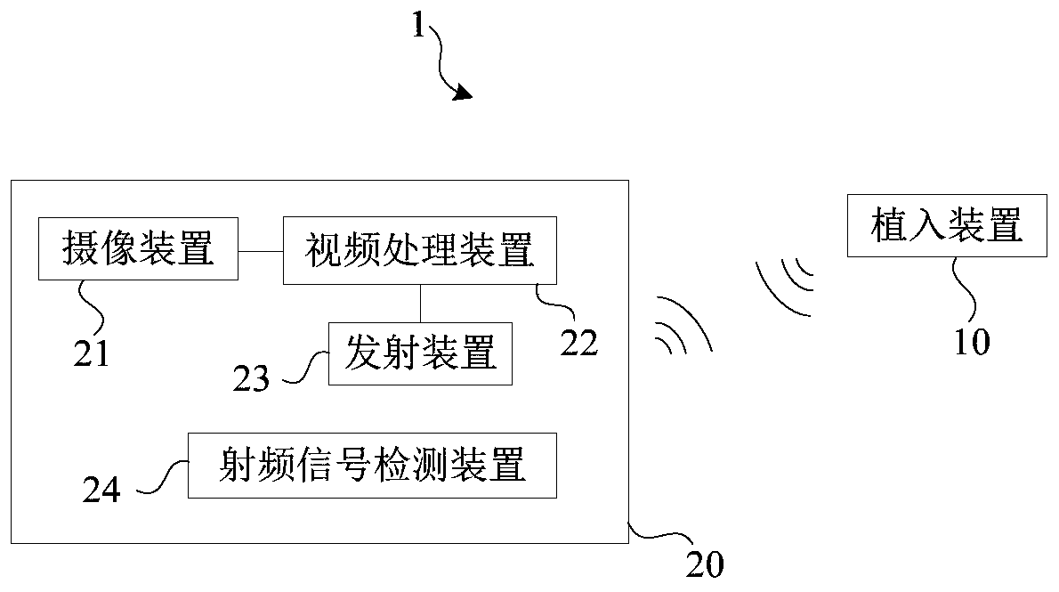
[0031] figure 1 It is a block diagram of the retinal stimulator according to this embodiment. The retinal stimulator...


PUM


Abstract

The invention discloses a radio frequency signal detection device with a detection coil. The radio frequency signal detection device is used for a retina stimulator comprising an implantation device and in vitro equipment with a transmitting coil. The radio frequency signal detection device is characterized by comprising a resonance circuit, a demodulation circuit, a comparison circuit and a processing module, wherein through the detection coil, the resonance circuit is used for receiving radio frequency signals generated by the implantation device, the radio frequency signals contain carrierwave signals and baseband signals, and the frequency of the carrier wave signals is larger than the frequency of the baseband signals; the demodulation circuit is used for extracting baseband signalsfrom the radio frequency signals; the comparison circuit is used for comparing the baseband signals with reference signals and a comparison result is obtained; and the processing module is used for monitoring the radio frequency signals based on the comparison result. According to the radio frequency signal detection device disclosed by the invention, the radio frequency signals generated by the implantation device can be effectively monitored.

Description

technical field [0001] The invention relates to the field of medical equipment, in particular to a radio frequency signal detection device with a detection coil and a retinal stimulator. Background technique [0002] The formation of normal vision is that the photoreceptor cells on the retina in the eyeball convert external light signals into visual signals. Visual signals reach the cerebral cortex via bipolar cells and ganglion cells, thereby forming light perception. However, in life, the whole pathway is blocked due to retinal diseases such as RP (retinitis pigmentosa), AMD (age-related macular degeneration), etc., resulting in decreased vision or blindness. [0003] In order to restore partial vision to patients, retinal stimulator technology came into being. Retinal stimulator technology uses electrical current to stimulate nerves that are still intact, allowing the brain to pick up the signal and think the senses are still working. [0004] With the research and dev...

Claims


Application Information

Patent Timeline
Patent Type & Authority Applications(China)
IPC IPC(8): A61N1/36
CPCA61N1/0543A61N1/36046A61N1/3727
Inventor 夏斌谭致赵瑜陈志钟灿武
Owner SHENZHEN SIBIONICS CO LTD
Why Eureka
Try Eureka