Visual prosthesis and retina stimulation device for same

Inactive Publication Date: 2012-04-26
PIXIUM VISION SA
View PDF2 Cites 1 Cited by
  • Summary
  • Abstract
  • Description
  • Claims
  • Application Information

AI Technical Summary

Benefits of technology

[0020]With regard to the elongated configuration of each electrode array in the lateral or transverse direction, the inventor has recognized that the conventional square electrode arrays do not achieve an optimum stimulation of the available nerve tissue in the retina. By re-designing the electrode array(s) of the retina stimulation device to have a significantly greater extent in the medial-lateral direction (i.e. width or breadth) than in the vertical direction (i.e. height), the inventor has been able to activate a greater number of retinal ganglion cells and achieve a greater virtual field of vision for a given area of the electrode array. As such, the invention provides a more optimal stimulation of the retina nerve cells and a more efficient electrode array configuration.
[0021]More particularly, the inventor has ascertained that an optimized use of the retina surface (e.g. th

Problems solved by technology

In practice, however, the energy level of the incident light proved

Method used


Image

  • Visual prosthesis and retina stimulation device for same
  • Visual prosthesis and retina stimulation device for same

Examples


Embodiment Construction

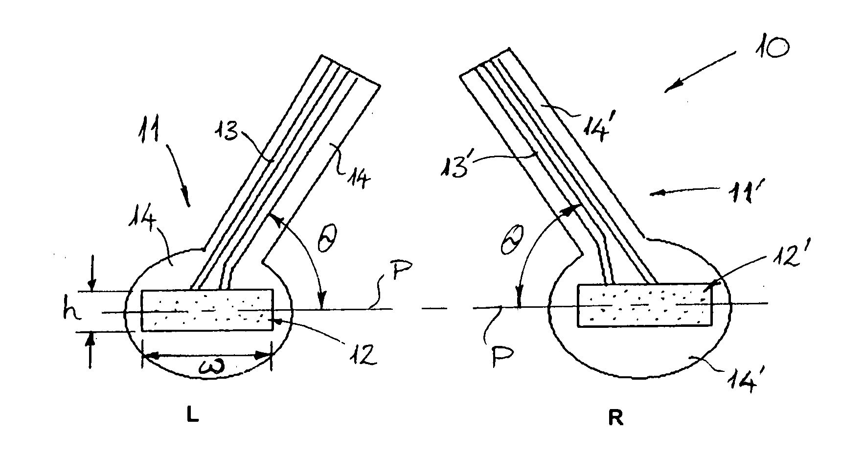
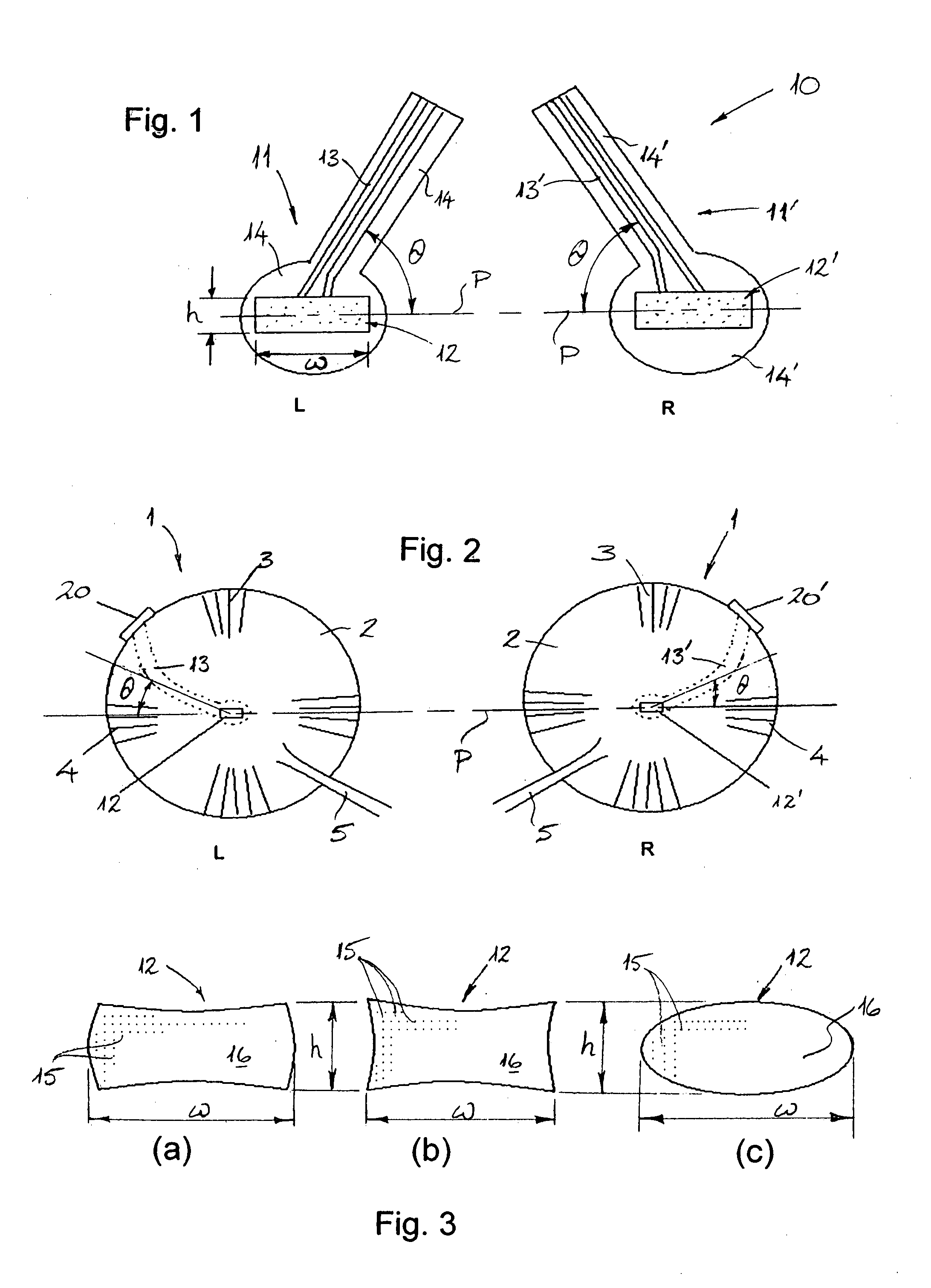
[0029]The visual prosthesis according to a preferred embodiment of the present invention incorporates both internal (i.e. implanted) components and external (i.e. non-implanted) components. In particular, the system architecture of the visual prosthesis according to the invention generally reflects the state-of-the-art design, in which a device resembling a pair of glasses or spectacles incorporates image capture means for capturing an image of the environment surrounding the user. According to this particular embodiment of the invention, the spectacles (not shown) incorporate an image capture means in the form of a left-side camera and a right-side camera, the two cameras being spaced apart from one another at opposite (i.e. left and right) sides of the spectacles; for example, in or adjacent the respective arm members of the frame of the spectacles.

[0030]The visual prosthesis furthermore includes an external processor device (not shown) which is preferably designed to be carried b...


PUM


Abstract

The present invention provides a visual prosthesis comprising: image capture means for capturing an image from a surrounding environment; image processing means for processing the image and converting the image into a transmissible image signal; signal processing means for processing and converting the image signal into a stimulation signal; and a retina stimulation device (10) adapted to stimulate the retina of both left and right eyes in accordance with the stimulation signal. The retina stimulation device (10) comprises a left-side stimulation unit (11) having an electrode array (12) for stimulating the retina of the left eye, and a right-side stimulation unit (11′) having an electrode array (12′) for stimulating the retina of the right eye, with the left-side stimulation unit (11) having a configuration which is reversed with respect to a configuration of the right-side stimulation unit (11′). Furthermore, the electrode array (12) has a plurality of individual electrodes (15) distributed in a predetermined pattern across a substrate (16) of the electrode array for stimulating the nerve cells of the retina. The electrode array substrate (16) is elongate in a lateral or transverse direction, namely in a medial-lateral direction with respect to an implantation orientation, such that the electrode array has a height-to-width ratio of less than 1, preferably less than 0.8, more preferably in the range of 0.6 to 0.2, and most preferably in the range of about 0.5 to about 0.3.

Description

TECHNICAL FIELD[0001]The present invention relates to a visual prosthesis, and more particularly to a visual prosthesis for restoring vision to patients afflicted with certain diseases leading to degeneration of the retina. The invention also relates to a retina stimulation device for use in such a visual prosthesis.BACKGROUND ART[0002]In the course of about the last fifteen years, concerted efforts have been made to develop techniques and devices for restoring vision in patients afflicted by certain diseases. In patients suffering from macula degeneration and retinitis pigmentosa, both of which diseases lead to a loss of retina function over a period of time and ultimately cause total blindness, it has been discovered that substantial parts of the nervous system of the eye, including the optic nerve and the sub-retinal neurons, actually remain intact and fully functional. Since the early days of research and development in this field, therefore, a number of different techniques and...

Claims


Application Information

Patent Timeline
IPC IPC(8): A61F9/08A61N1/36
CPCA61N1/0543A61N1/36046
Inventor TIEDTKE, HANS-JURGEN
Owner PIXIUM VISION SA
Why Eureka
Try Eureka