
Frame unit

a frame unit and frame technology, applied in the field of frame units, can solve the problems of a higher weight of the frame unit, and achieve the effect of high connection strength and sufficient strength

Active Publication Date: 2020-12-29
SAF HOLLAND GMBH
View PDF40 Cites 0 Cited by
  • Summary
  • Abstract
  • Description
  • Claims
  • Application Information

AI Technical Summary

Benefits of technology

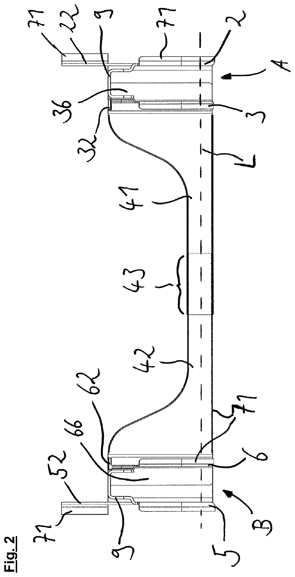
[0005]In this case, the transverse region preferably has an extent along or parallel in relation to the bearing axis which is at least 1.5 times, preferably 2 to 4 times, the distance of the inner bearing region from the outer bearing region. With this preferred extent of the transverse region, said transverse region can transmit quiescent moments. In this case, the bending moments on the frame unit are introduced into the frame unit particularly by the longitudinal link of the utility vehicle, wherein a possible moment-transmitting region includes the bearing regions. The transverse region particularly preferably has an extent which is at least 1.5 times the distance of the two bearing regions from one another. In this way, the lever arm with which the transverse region can absorb moments is larger than the lever arm with which the axle guide transmits a moment about an orthogonal in relation to the bearing axis to the frame unit. This can result in secure support of the frame unit by the transverse region. The transverse region particularly preferably has a greater extent, this allowing transmission and safeguarding of higher moments, but has the disadvantage of a higher weight of the frame unit.
[0027]The first inner part advantageously has a first flange section and the second inner part advantageously has a second flange section, wherein the inner parts can be secured to a respective outer part by means of a flange section in each case. The inner part is advantageously connected to the respective outer part by means of a weld connection in the region of the flange section. Weld connections have the advantage that they achieve a high strength with a low additional increase in weight. If the ability to dismantle the frame system is preferred, the inner part can also be connected to the respective outer part by means of interlocking releasable connections, such as a screw connection for example, in the region of the flange section.

Problems solved by technology

The transverse region particularly preferably has a greater extent, this allowing transmission and safeguarding of higher moments, but has the disadvantage of a higher weight of the frame unit.

Method used


Image

  • Frame unit
  • Frame unit
  • Frame unit

Examples


Embodiment Construction

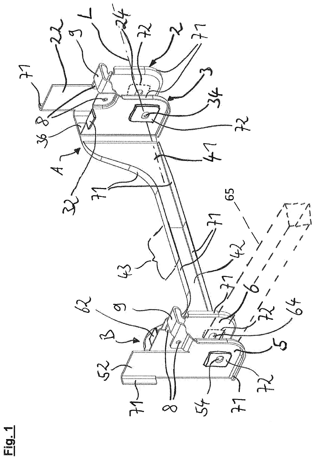
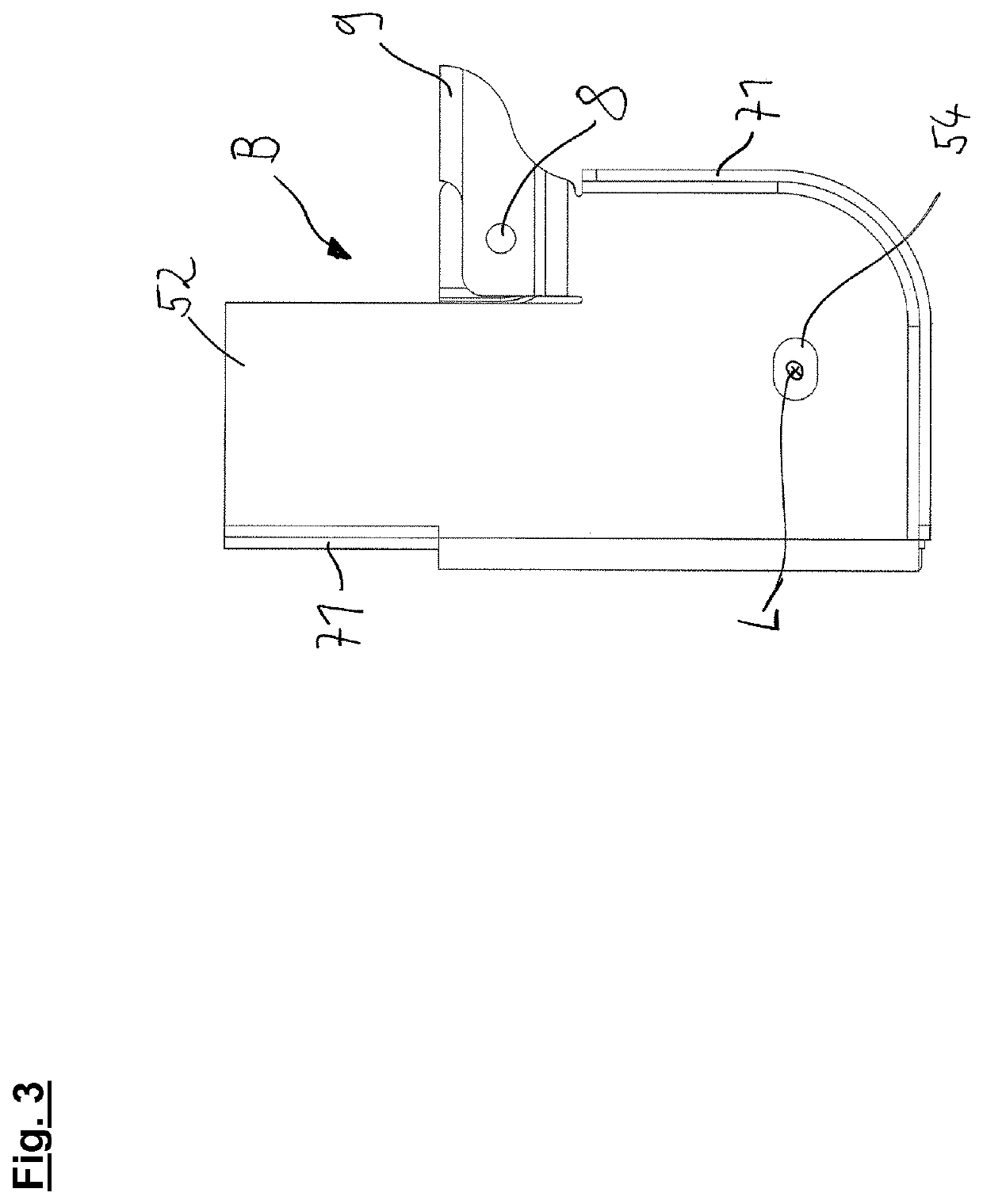
[0034]The frame system illustrated in FIG. 1 has a first frame unit A and a second frame unit B, wherein the first frame unit A has a first outer part 2, a first inner part 3 and a first transverse region 41. The second frame unit B accordingly has a second outer part 5, a second inner part 6 and a second transverse region 42. All of the components of the frame system are preferably of sheet metal-like design, that is to say they have a substantially lower extent in at least one spatial direction than in the other spatial directions. The first outer part 2 has an outer bearing region 24 and the first inner part has an inner bearing region 34. A longitudinal link of the utility vehicle chassis can be secured in a pivotable manner between the bearing regions 24, 34. In this case, the longitudinal link can be secured to the first frame unit A such that it can pivot about a bearing axis L. Analogously to this, the second outer part 5 has an outer bearing region 54 and the second inner p...


PUM


Abstract

A frame unit for utility vehicles includes outer and inner parts and a transverse region, wherein the transverse region extends substantially transversely to the outer part and / or the inner part, wherein the transverse region is integrally formed with the outer part or the inner part, the outer part and / or the inner part has a fastening region for being secured to a vehicle frame, the outer part has an outer bearing region and the inner part has an inner bearing region, an axle guide can be arranged between the outer and inner bearing regions and can be secured to the bearing regions such that the axle guide can pivot about a bearing axis, and wherein the transverse region secures the outer part and / or the inner part against pivoting about an orthogonal in relation to the bearing axis.

Description

BACKGROUND OF THE INVENTION[0001]The present invention relates to a frame unit and to a frame system for use in motor vehicles, in particular in utility vehicles.[0002]Frame units themselves are already known from the prior art. In particular, bearing blocks which establish a connection between the longitudinal link of a vehicle chassis and the frame of the vehicle are used as a frame unit in the prior art. In this case, the bearing blocks are usually welded to the frame of the vehicle or secured to said frame by means of a screw or bolt connection. In most cases, stabilization of the bearing block by additional supporting elements which additionally have to be secured to the bearing block is required here. It has been found here that the bearing blocks known from the prior art are oversized and, in particular, cannot be adapted to local stress peaks. Furthermore, a large amount of expenditure on assembly is required for the bearing blocks known from the prior art in order to firstl...

Claims


Application Information

Patent Timeline
Patent Type & Authority Patents(United States)
IPC IPC(8): B62D21/02B62D21/00B60G7/02B60G9/00B60G11/10
CPCB60G9/003B60G7/02B60G11/10B60G2204/143B60G2206/8103B60G2206/601B62D21/00B60G2206/722B62D21/02
Inventor BORDE, FLORIANARPACI, MUHAMMETBERGMANN, PHILIPP
Owner SAF HOLLAND GMBH
Learn More