
Coupling joint structure of small-sized boat

a small-sized boat and coupling joint technology, applied in the direction of couplings, marine propulsion, vessel construction, etc., can solve the problems of difficult to secure the durability of the pawl pieces, and achieve the effect of reducing the centrifugal for

Inactive Publication Date: 2006-09-14
HONDA MOTOR CO LTD
View PDF3 Cites 27 Cited by
  • Summary
  • Abstract
  • Description
  • Claims
  • Application Information

AI Technical Summary

Benefits of technology

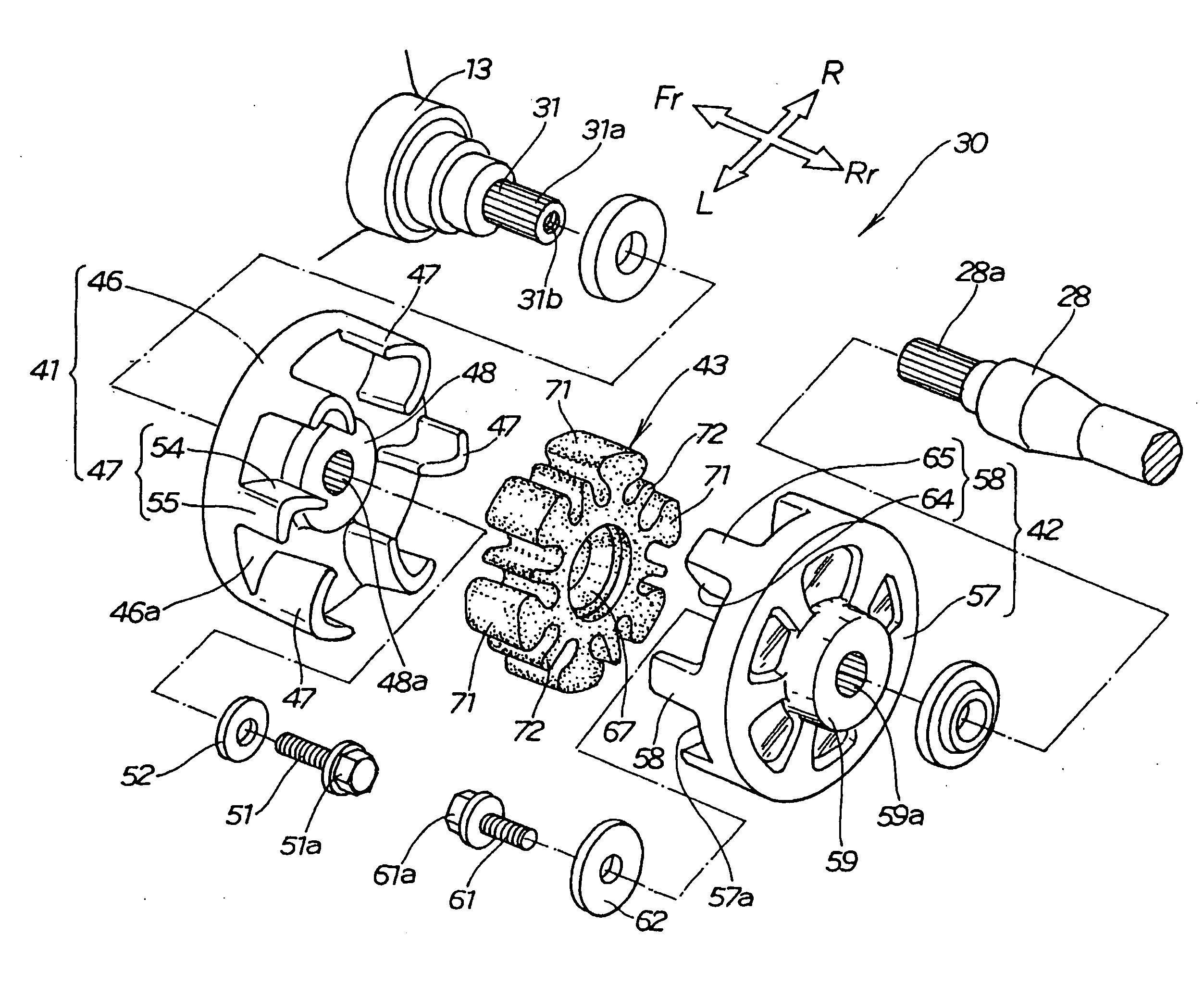
[0016] The object of the invention is to provide coupling joint structure of a small-sized boat where the output of an engine can be securely transmitted to a propeller shaft and centrifugal force can be reduced.
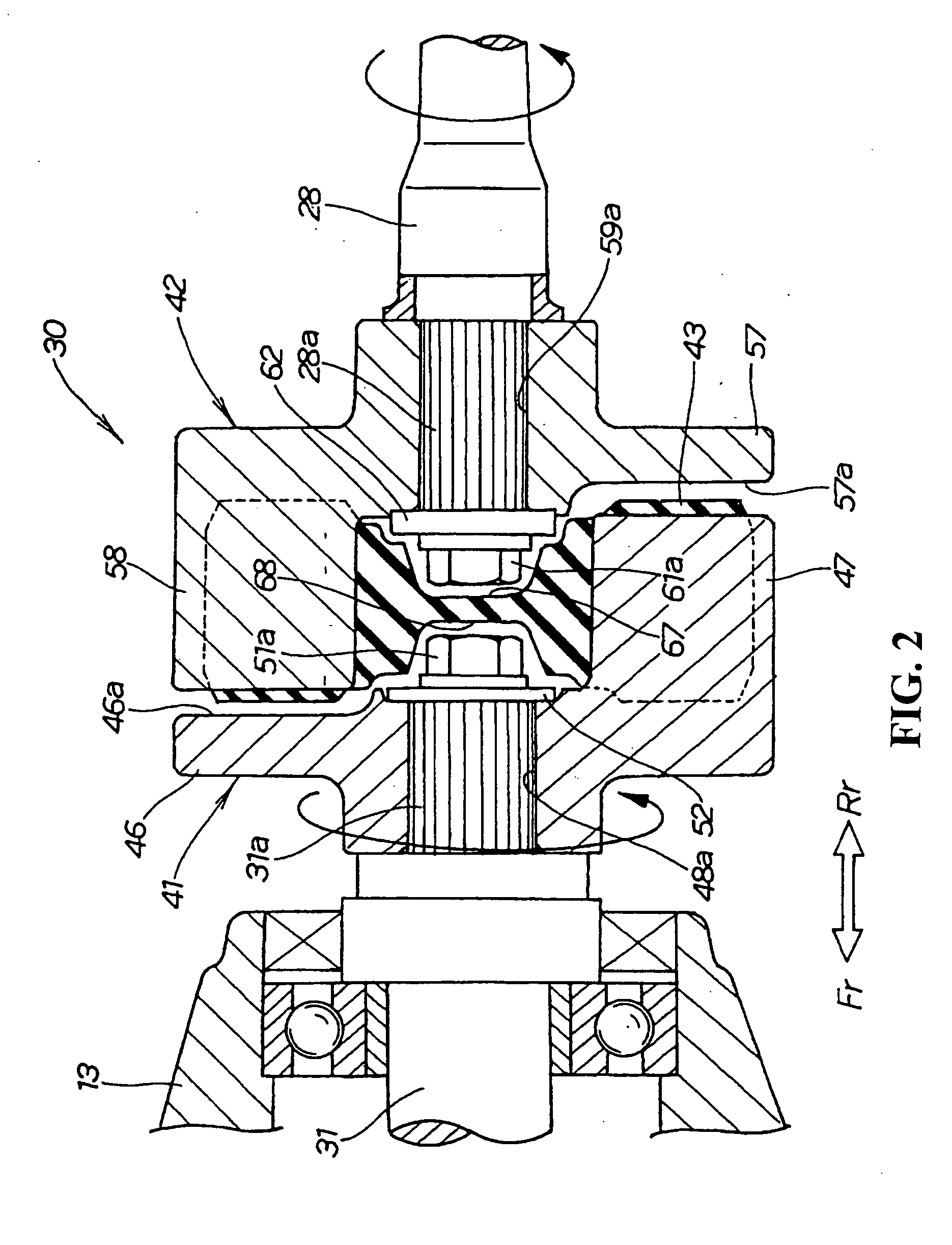
[0023] Hereby, when the revolution of the engine is transmitted to the propeller shaft, the centrifugal force of the pawl piece on the driving side and the pawl piece on the driven side can be reduced.
[0026] Hereby, the rigidity of the damper member can be secured to the same extent as that of the conventional type and the revolution of the engine can be securely transmitted to the propeller shaft.
[0027] As a result of first aspect of the present invention, the output of the engine can be securely transmitted to the propeller shaft by securely supporting a load applied to the pawl piece on the driving side and the pawl piece on the driven side by the respective pawl pieces.
[0028] The first aspect of the present invention also has an advantage that the durability of the pawl piece on the driving side and the pawl piece on the driven side with centrifugal force can be easily secured by reducing the centrifugal force of the pawl piece on the driving side and the pawl piece on the driven side.
[0029] According to the second aspect of the present invention, the revolution of the engine can be securely transmitted to the propeller shaft by securing the rigidity of the damper member to the same extent as that of the conventional type.

Problems solved by technology

Therefore, it is difficult to secure the durability of the pawl pieces 107 - - - , 109 - - - with centrifugal force.

Method used


Image

  • Coupling joint structure of small-sized boat
  • Coupling joint structure of small-sized boat
  • Coupling joint structure of small-sized boat

Examples


Embodiment Construction

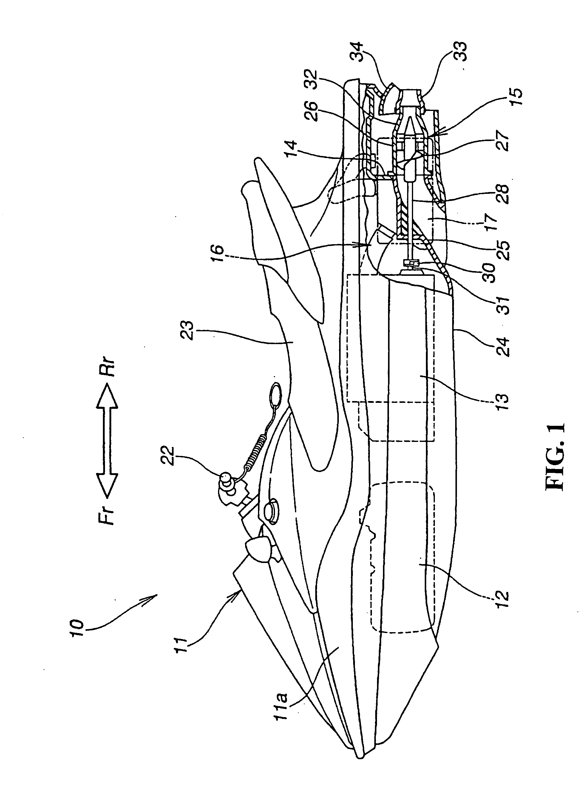
[0039] Referring to the attached drawings, a best embodiment for embodying the invention will be described below. A forward direction, a backward direction, a leftward direction and a rightward direction denote a direction viewed from a rider, Fr denotes the front side, Rr denotes the rear side, L denotes the left side, and R denotes the right side.

[0040]FIG. 1 is a side view showing a small-sized boat provided with coupling joint structure according to the invention.

[0041] The small-sized boat 10 is a water jet propulsion boat which is provided with a fuel tank 12 in the front 11a of the body 11, which is provided with an engine 13 at the back of the fuel tank 12, which is provided with a pump case 14 at the back of the engine 13, which is provided with a water jet pump 15 in the pump case 14, in which the water jet pump (a propeller) 15 is coupled to the engine 13 using coupling joint structure 30, an inlet of an exhaust pipe 16 is attached to the engine 13 and an outlet of the ...


PUM


Abstract

A coupling joint structure for a boat where the output of an engine can be securely transmitted to a propeller shaft and centrifugal force can be reduced. The structure includes a first coupler on the driving side to an output shaft, a second coupler on the driven side to a propeller shaft, and a damper member interposed between the second coupler on the driven side and the first coupler on the driving side. The first coupler on the driving side and the second coupler on the driven side each include pawl pieces. In a first curved part of each of the pawl pieces on the driving side, the base (wall thickness t1) is made thicker than the end (wall thickness t2). In a second curved part of each of the pawl pieces on the driven side, the base (wall thickness t1) is made thicker than the end (wall thickness t2).

Description

CROSS-REFERENCE TO RELATED APPLICATION [0001] The present application claims priority under 35 U.S.C. §119 to Japanese Patent Application No. 2005-069246, filed Mar. 11, 2005, the entire contents of which are hereby incorporated by reference. BACKGROUND OF THE INVENTION [0002] 1. Field of the Invention [0003] The present invention relates to coupling joint structure of a small-sized boat where respective couplers are provided to an output shaft and a propeller shaft, a damper member is interposed between each coupler and the revolution of the output shaft is transmitted to the propeller shaft via the damper member. [0004] 2. Description of Background Art [0005] A small-sized boat is provided in which an engine is mounted in the body of the boat, a water jet pump is provided at the back of the engine and an output shaft of the engine is coupled to a propeller shaft of the water jet pump via a coupling. [0006] The revolution of the output shaft is transmitted to the propeller shaft vi...

Claims


Application Information

Patent Timeline
IPC IPC(8): B63H23/34F16D3/68
CPCB63H23/34F16D3/68
Inventor FUSE, TOMOHIRO
Owner HONDA MOTOR CO LTD
Learn More