Rotor of electric rotating machine

a rotating machine and electric technology, applied in the direction of magnetic circuit rotating parts, synchronous generators, magnetic circuit shape/form/construction, etc., can solve the problems of reducing the service life reducing the weight of the claw magnetic pole as a whole, and reducing the change in position due to vibration, so as to prevent the magnet-holding members from falling off, the effect of reducing the deformation of the claw magnetic pol

Inactive Publication Date: 2006-05-11
MITSUBISHI ELECTRIC CORP
View PDF10 Cites 13 Cited by
  • Summary
  • Abstract
  • Description
  • Claims
  • Application Information

AI Technical Summary

Benefits of technology

[0021] The present invention was made to solve the above-discussed problems and has an object of providing a rotor structure in which fitting structure of the magnets for preventing leakage of magnetic flux between the claw magnetic poles is designed so as to reduce centrifugal force caused by rotation of the rotor, reduce deformation and vibration of the claw magnetic poles, thus improving efficiency in assembling the rotor.
[0023] As a result, deformation of the claw magnetic poles is reduced, and change in position due to vibration is also reduced and, therefore, it is possible to prevent the magnet-holding members from breaking and prevent the magnet assembly from getting out, and the air gap between the rotor and the stator can be reduced. Consequently, it is possible to improve the output.

Problems solved by technology

As a result, a load is applied to the magnets between the claw poles, and this sometimes may cause distortion or breakage of the magnets.
However, fitting the magnets brings about a contrary effect, i.e., the claw magnetic pole as a whole increases in weight and the claw magnetic pole receives more centrifugal force caused by rotation of the rotor.
In the meanwhile, the magnet-holding members for fitting the magnets to the claw magnetic poles are influenced by the deformation of the claw magnetic poles and change in number of rotation of the rotor, and there is a possibility that the magnet-holding members or the magnets themselves are broken or get out of position due to vibration of the claw magnetic poles.
Moreover, the known structure of fitting the magnets to the claw magnetic poles also has a problem that it is not possible to efficiently assemble the rotor because interference in magnetic position occurs between the pole cores at the time of assembling the rotor.

Method used


Image

  • Rotor of electric rotating machine
  • Rotor of electric rotating machine
  • Rotor of electric rotating machine

Examples


embodiment 1

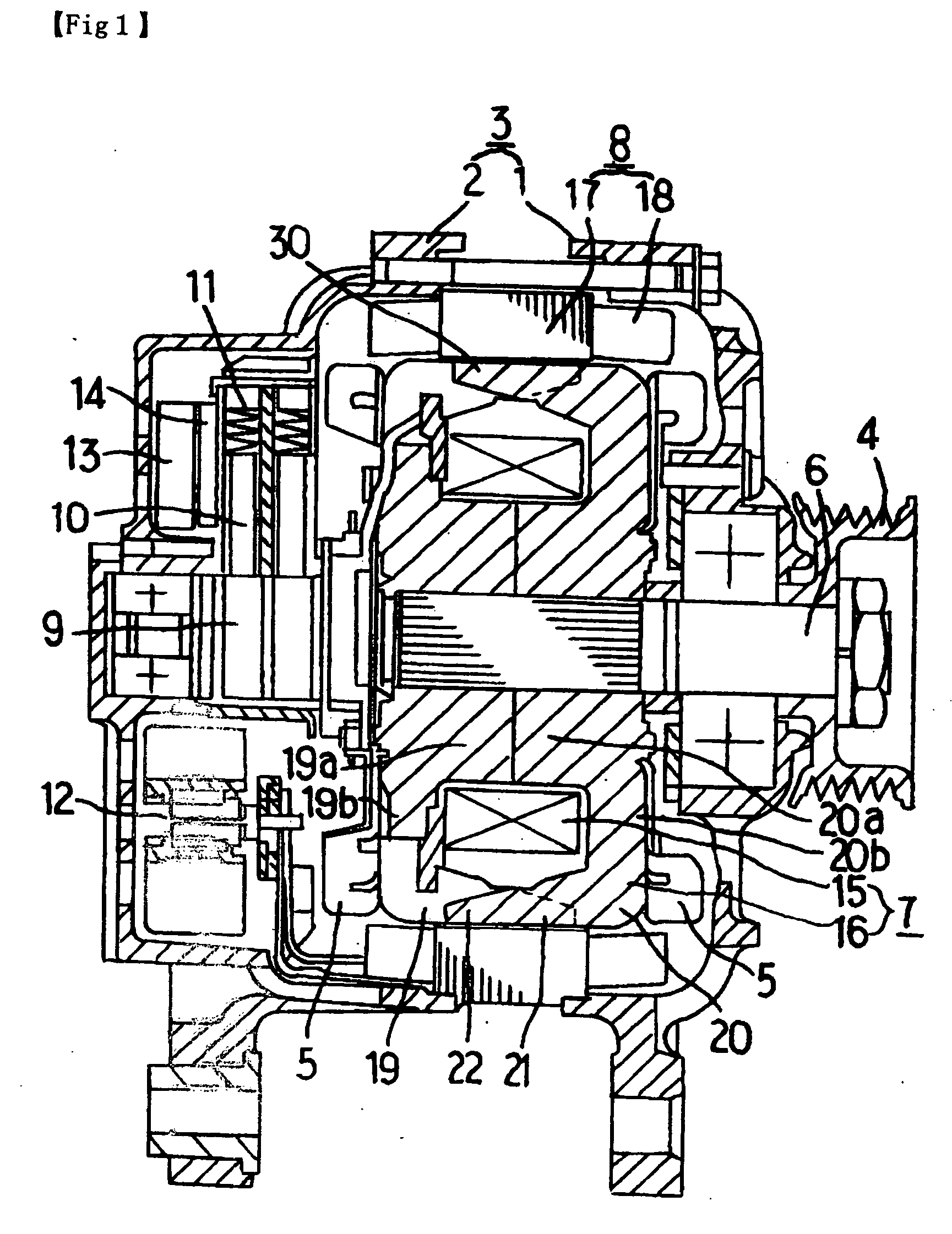
[0034]FIG. 1 is a sectional side view showing an electric rotating machine in its entirety such as an ac generator or an electric motor according to one embodiment of the present invention. Referring to the drawing, this electric rotating machine is provided with a housing 3 comprised of a front bracket 1 and a rear bracket 2 both made of aluminum, a shaft 6 disposed in this housing 3 and provided with a pulley 4 fixed onto an end thereof, a Randell-type rotor 7 fixed onto this shaft 6, fans 5 fixed onto both end faces of this rotor 7, a stator 8 fixed onto an inner wall face in the housing 3, a slip ring 9 that is fixed to the other end of the shaft 6 and supplies the rotor 7 with a current, a pair of brushes 10 sliding on this slip ring 9, a brush holder 11 in which these brushes 10 are accommodated, a rectifier 12 that is electrically connected to the stator 8 and rectifies an alternating current generated in the stator 8 into a direct current, a heat sink 13 fitted to the brush ...

embodiment 2

[0063] In the foregoing Embodiment 1, the magnet assembly is constructed so as to cover the whole side of the claw magnetic poles and, furthermore, the center of gravity is located near the base side. In this Embodiment 2, however, not only the center of gravity of the magnet assembly, but also the magnet assembly itself is disposed near the base side of the claw magnetic poles; thus, the whole magnet assembly is located on the base side.

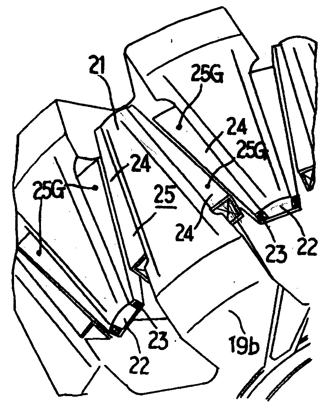
[0064] More particularly, as shown in FIG. 3, the claw magnetic pole 21 is provided with magnet assembly 25a only on both sides of the base part 19b, and the claw magnetic pole 22 is provided with magnet assembly 25b only on both sides of the base part 20b.

[0065] By employing the construction as described above, centrifugal force on the claw magnetic poles 21, 22 increases only on the base side and, therefore, the end of the claw magnetic poles 21, 22 receives less centrifugal force and deformation thereof becomes small. The air gap between the ro...

embodiment 3

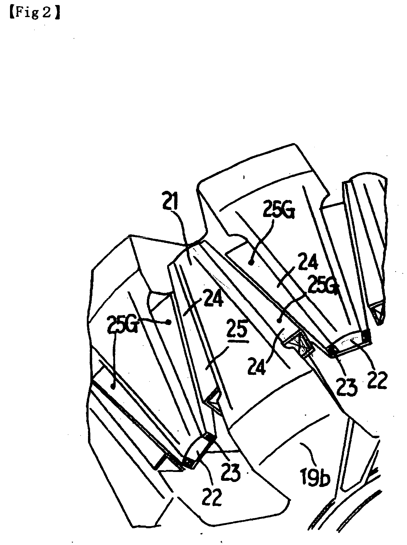
[0070]FIG. 4 is a partial perspective view showing a rotor portion according to Embodiment 3 of the invention, and FIG. 5 is a perspective view showing a claw magnetic pole portion.

[0071] In this embodiment, the magnet-holding members extend to the base side along both side faces of the claw magnetic poles 21, 22.

[0072] These extending portions are adhered to the claw magnetic poles 21, 22 with an adhesive agent or welded thereto.

[0073] By employing the construction as described above, the magnet assemblies are fixed more firmly than those of the foregoing Embodiments 1 and 2 and, furthermore, rotation of the claw magnetic poles 21, 22 in the circumferential direction is restrained.

[0074] Furthermore, it is possible to arrange the magnets 23 on the extending portions, thereby further reducing leakage of magnetic flux.

[0075] As described above, according to this embodiment, since the magnet assemblies 25 extend to the base parts of the claw magnetic poles 21, 22, the claw magnet...


PUM


Abstract

Deformation and vibration of claw magnetic poles in rotor are reduced. A rotor includes: a rotor coil 15 for generating a magnetic flux by applying a current; a pole core comprised of a first pole core body 19 and a second pole core body 20 that are disposed so as to cover the rotor coil 15, each being provided with claw-shaped claw magnetic poles 21, 22 engaging with each other; and a magnet assembly 25 composed of a magnet 23 for reducing leakage of magnetic flux and a magnet-holding member 24 for supporting the magnet 23 on the claw magnetic poles 21, 22. Center of gravity 25G of the magnet assembly 25 is located on the base part side nearer than the center of the claw magnetic poles 21, 22.

Description

BACKGROUND OF THE INVENTION [0001] This is a divisional application of Ser. No. 10 / 663,775 filed Sep. 17, 2003. The entire disclosure of prior application Ser. No. 10 / 663,775 is considered part of the disclosure of the accompanying divisional application and is hereby incorporated by reference. [0002] 1. Field of the Invention [0003] The present invention relates to a rotor structure of an electric rotating machine such as an ac generator or an electric motor and, more particularly, to a structure of fitting a magnet that prevents leakage of magnetic flux between claw magnetic poles. [0004] 2. Description of the Related Art [0005] In a conventional rotor structure, rectangular parallelepiped magnets polarized in a direction of reducing leakage of magnetic flux between sides of adjacent claw magnetic poles are fixed between the claw magnetic poles facing each other, and holders for reducing centrifugal force are used to fit these magnets. [0006] When the magnets for preventing leakag...

Claims


Application Information

Patent Timeline
Patent Type & Authority Applications(United States)
IPC IPC(8): H02K1/22H02K19/22
CPCH02K21/044
Inventor MAEDA, NAOHIDEASAO, YOSHIHITO
Owner MITSUBISHI ELECTRIC CORP
Why Eureka
Try Eureka