Planetary transmission having a rotating-type torque-transmitting mechanism with a stationary piston

a technology of rotating-type torque-transmitting mechanism and stationary piston, which is applied in mechanical actuated clutches, sealing assemblies, and sealing, etc., can solve the problems of frictional loss within the seal assembly, inability to engage the clutch, and inability to so as to reduce or eliminate the centrifugal force, improve the packaging arrangement, and reduce the axial space requirement

Active Publication Date: 2006-07-04
GM GLOBAL TECH OPERATIONS LLC
View PDF5 Cites 14 Cited by
  • Summary
  • Abstract
  • Description
  • Claims
  • Application Information

AI Technical Summary

Benefits of technology

[0015]In yet still a further aspect of the present invention, a power transmission having a plurality of stationary piston-type rotating torque-transmitting mechanisms provides an improved packaging arrangement by reducing the axial space requirement for the torque-transmitting mechanisms.
[0016]The present invention provides rotating-type torque-transmitting mechanisms (clutches) each having a stationary piston. The stationary piston eliminates the need for rotating-type oil transfer structures and also the need for reducing or eliminating centrifugal forces that the oil might apply to the piston. The rotating-type torque-transmitting mechanisms with stationary pistons require less space and reduced mass, and they eliminate drag losses between the rotating shaft seals and the rotating housing. By reducing or eliminating the centrifugal effects, an improved controllability is permitted with the transmission system.

Problems solved by technology

The piston apply chamber is generally full of oil when the piston is not actuated and is subjected in many cases to centrifugal force which could cause the piston to apply, thereby partially engaging the clutch and inducing wear on the friction plates.
At times during operation, these two members will be rotating at different speeds, thereby creating a frictional loss within the seal assembly, which is termed as a drive loss within the transmission.

Method used


Image

  • Planetary transmission having a rotating-type torque-transmitting mechanism with a stationary piston
  • Planetary transmission having a rotating-type torque-transmitting mechanism with a stationary piston
  • Planetary transmission having a rotating-type torque-transmitting mechanism with a stationary piston

Examples


Embodiment Construction

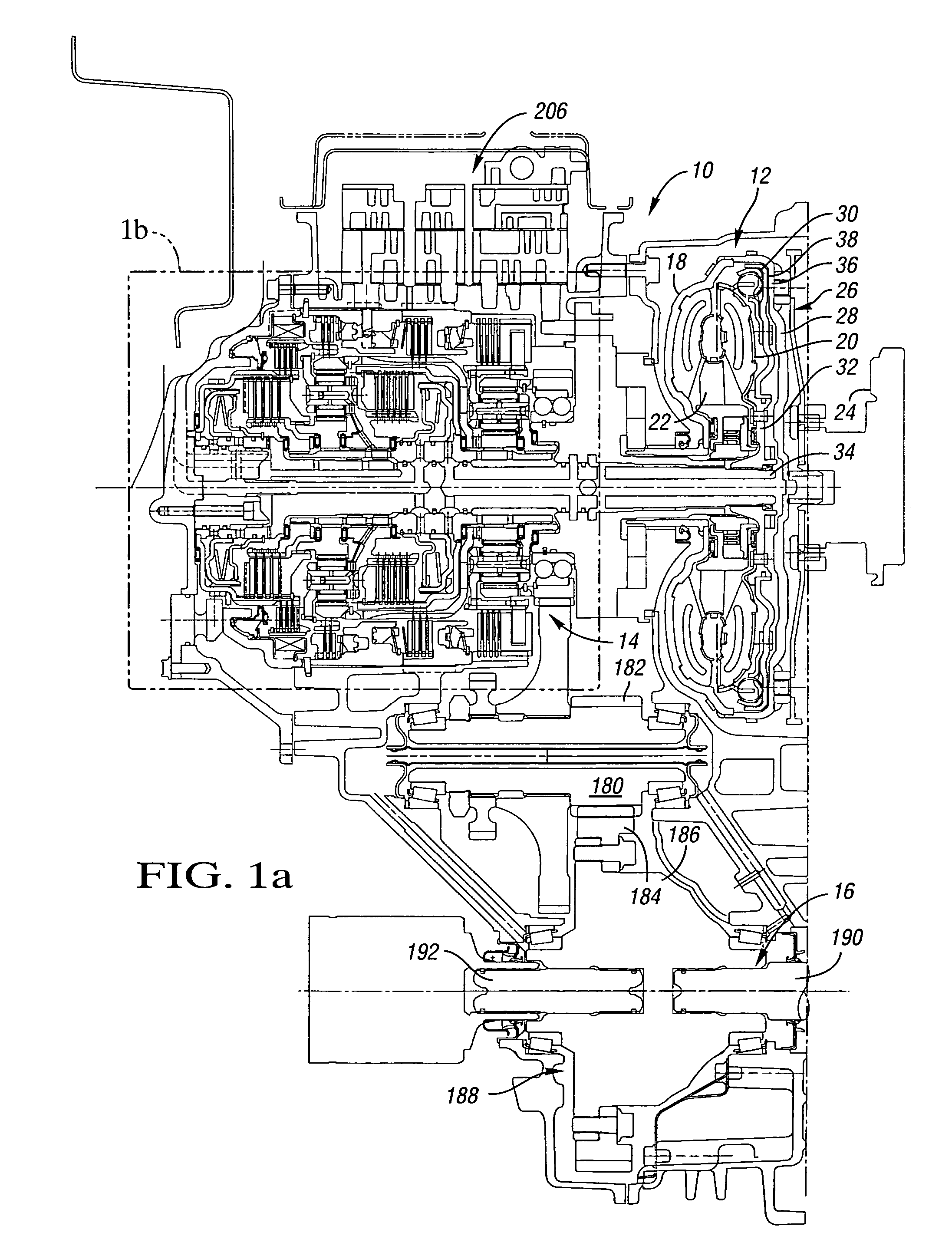
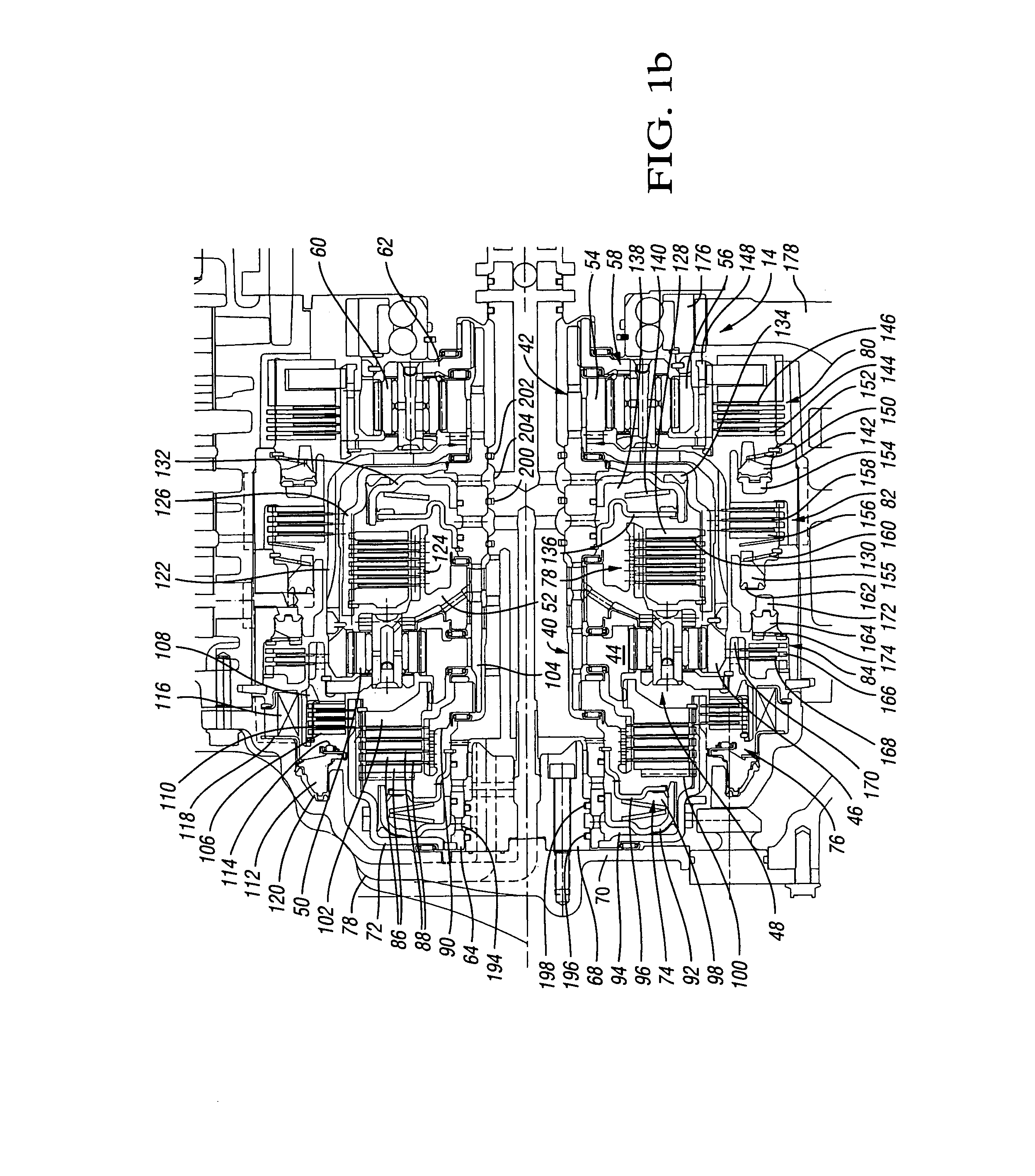
[0024]Referring to the drawings, there is shown in FIGS. 1a and 1b a planetary transmission 10, which includes a conventional torque converter 12, planetary gear arrangement 14, and a final drive mechanism 16. The torque converter 12 includes an impeller 18, a turbine 20, and a stator 22. The impeller 18 is connected with an engine crankshaft 24 through a flex plate 26 and an input shell 28. A conventional torque converter clutch 30 is disposed between the turbine 20 and the input shell 28. The torque converter clutch 30 has one portion secured to the turbine 20 and includes a hub 32, which is splined to a transmission input shaft 34. The torque converter clutch 30 has an apply plate 36, which includes a friction surface 38 that engages the inner surface of the input shell 28. When the torque converter clutch is applied, as is well known, a direct drive between the engine crankshaft 24 and the transmission input shaft 34 is provided. During torque converter operation, a hydrodynamic...


PUM


Abstract

A planetary transmission has a plurality of rotating-type torque-transmitting mechanism that are operable to connect a rotating input mechanism with one or more planetary gear members. At least two of the rotating-type torque-transmitting mechanisms are radially stacked and axially aligned. At least one of the radially stacked rotating torque-transmitting mechanisms has an apply piston that is slidably mounted in a stationary transmission housing, an apply plate that is rotatable with a portion of the torque-transmitting mechanism, and a bearing disposed therebetween to accommodate relative rotation therebetween.

Description

CROSS-REFERENCE TO RELATED APPLICATION[0001]This application claims the benefit of U.S. Provisional Application 60 / 498,269, filed Aug. 26, 2003, which is hereby incorporated by reference in its entirety.TECHNICAL FIELD[0002]This invention relates to rotating-type torque-transmitting mechanisms in power transmissions, especially rotating-type torque-transmitting mechanisms having a stationary piston.BACKGROUND OF THE INVENTION[0003]Power transmissions generally utilize one or more rotating-type torque-transmitting mechanisms, commonly termed clutches. The clutch assembly generally includes a piston slidably disposed in a housing, a plurality of interdigitated friction discs, one splined with a housing and the other splined with a hub, and a backup plate splined to one of the members.[0004]The piston is normally rotated with one of the housing members. A fluid pressure is applied between the housing and the piston into an apply chamber to cause the piston to engage with a pressure pla...

Claims


Application Information

Patent Timeline
Patent Type & Authority Patents(United States)
IPC IPC(8): F16H31/00F16D25/08F16H61/686F16H63/30
CPCF16D25/082F16H63/3026F16H61/686F16H2200/2015F16H2200/0052F16H2200/2007F16H2200/201F16H2200/0047F16D25/10
Inventor STEVENSON, PAUL D.HAKA, RAYMOND J.
Owner GM GLOBAL TECH OPERATIONS LLC
Why Eureka
Try Eureka