
Rolling-element bearing and method of manufacturing thereof

a technology of rolling-element bearings and bearings, which is applied in the direction of manufacturing tools, furnaces, heat treatment equipment, etc., can solve the problems of affecting the lifespan of rolling-element bearings, prone to premature failure, so as to achieve good cyclical loadability, good molding properties, and economic (cost-effective) manufacture

Active Publication Date: 2014-07-31
AB SKF
View PDF13 Cites 14 Cited by
  • Summary
  • Abstract
  • Description
  • Claims
  • Application Information

AI Technical Summary

Benefits of technology

The patent text describes a manufacturing method for bearing components that reduces susceptibility to crack formation and hinders the penetration of hydrogen. The method also reduces friction, energy losses, and the negative effects of direct material contact between rolling elements. In addition, the compressive residual stresses in the inner-ring raceway reduce the tendency of the inner ring to crack and increase service life of the rolling-element bearing.

Problems solved by technology

In particular with rolling-element bearings which are subjected to complex loading patterns, such as for example rolling-element bearings in industrial transmissions of wind turbines, cranes, or mills as well as paper machines and ship's reversing gearboxes, premature failures often occur, e.g., at between 1% and 25% of the nominal L10 lifespan (based on 90% reliability).
Thus, there is a long-felt need to provide a rolling-element bearing which has a long service life and a low risk of premature failure, even in operations involving extreme loading situations.
In particular in cases of extreme surface loading (and / or, e.g. also with contaminated lubricant), these improvement positively affect the lifespan of the rolling-element bearing.

Method used


Image

  • Rolling-element bearing and method of manufacturing thereof
  • Rolling-element bearing and method of manufacturing thereof
  • Rolling-element bearing and method of manufacturing thereof

Examples


Embodiment Construction

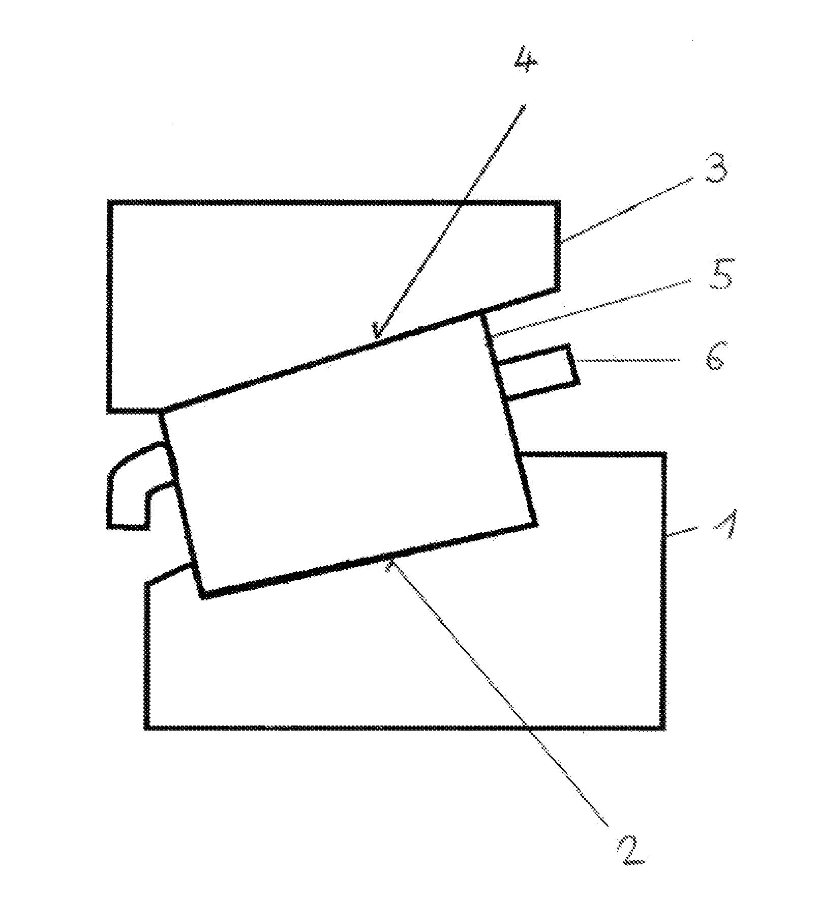
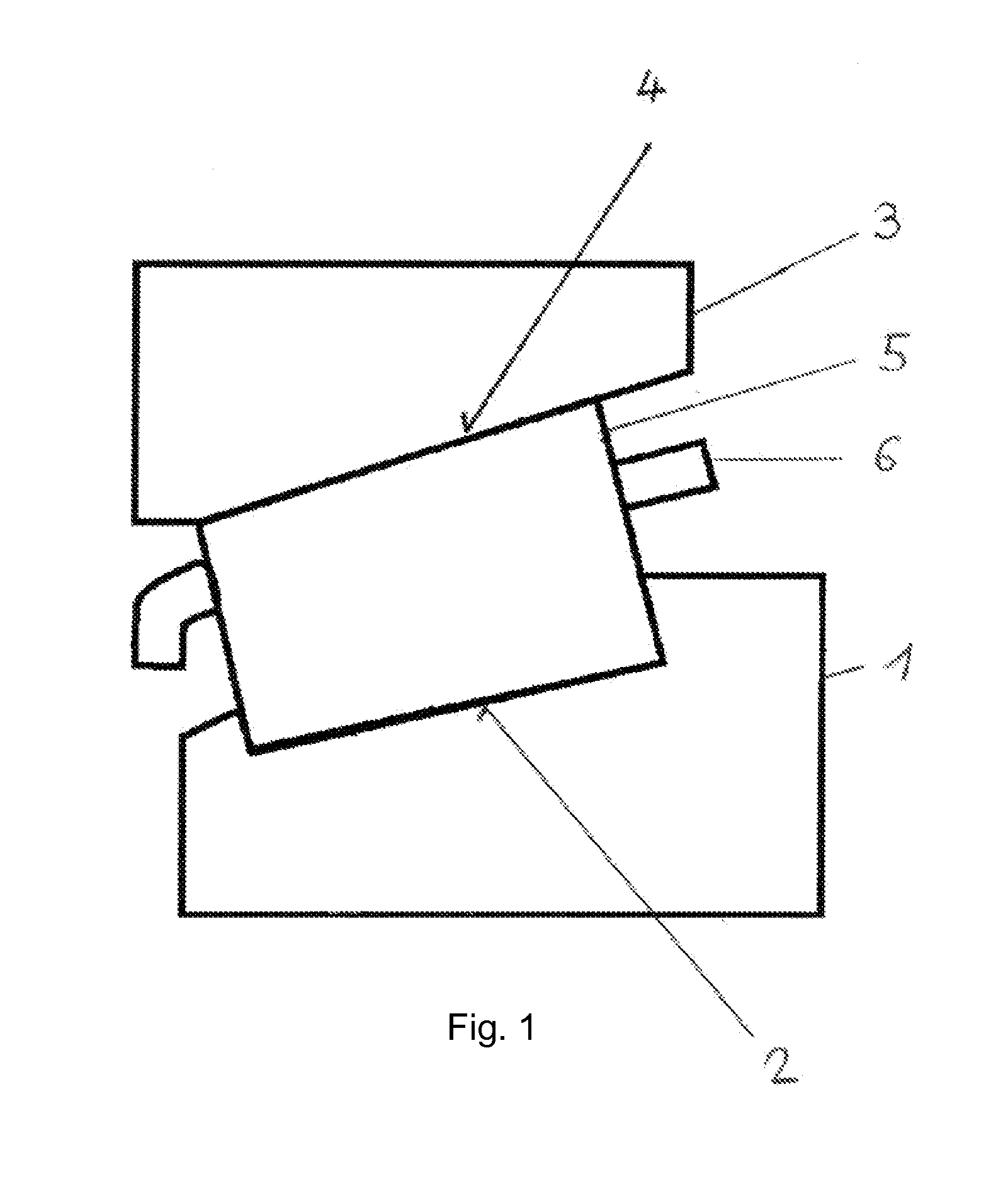
[0036]FIG. 1 shows an exemplary embodiment of a rolling-element bearing in a schematic sectional view. The depicted rolling-element bearing is formed as a tapered roller bearing and includes an inner ring 1 having a conical inner-ring raceway 2 and an outer ring 3 having a conical outer-ring raceway 4. Conical rolling elements 5 roll on the inner-ring raceway 2 and the outer-ring raceway 4. The rolling elements 5 are guided in a cage 6. Such a rolling-element bearing can for example be used in a transmission of a wind turbine.

[0037]As an alternative to the depicted exemplary embodiment, the rolling-element bearing can for example also be formed as a cylindrical roller bearing with cylinder-shaped rolling elements 5, or as a ball bearing with balls as rolling elements 5.

[0038]The inner ring 1 of the rolling-element bearing can be manufactured from a through-hardened steel, for example from the rolling-element bearing steel 100Cr6. Similarly, the inner ring 1 can be manufactured from ...


PUM

PropertyMeasurementUnit
Fractionaaaaaaaaaa
Percent by massaaaaaaaaaa
Pressureaaaaaaaaaa

Abstract

A rolling-element bearing includes an inner ring made of steel and having an inner-ring raceway, an outer ring having an outer ring raceway, and ceramic rolling elements which roll on the inner-ring raceway and on the outer-ring raceway. The inner ring has been subjected to a heat treatment to harden it. The heat treatment is concluded with the performance of a final heat-treatment step at a predetermined temperature. In the inner ring, compressive residual stresses are formed in an outer layer by cold working in the region of the inner-ring raceway. The inner ring also has been subjected to a bluing treatment.

Description

CROSS-REFERENCE[0001]This application claims priority to German patent application no. 10 2013 201 321.3 filed on Jan. 28, 2013, the contents of which are incorporated herein by reference.TECHNICAL FIELD[0002]The present disclosure generally relates to rolling-element bearings and to methods for manufacturing such rolling-element bearingsRELATED ART[0003]In particular with rolling-element bearings which are subjected to complex loading patterns, such as for example rolling-element bearings in industrial transmissions of wind turbines, cranes, or mills as well as paper machines and ship's reversing gearboxes, premature failures often occur, e.g., at between 1% and 25% of the nominal L10 lifespan (based on 90% reliability). In view of the high costs of the rolling-element bearings themselves (usually larger roller bearings), the repair costs (e.g. offshore wind turbines) and the high costs caused by a shutdown of systems equipped with such rolling-element bearings, a longer, more prob...

Claims


Application Information

Patent Timeline
IPC IPC(8): F16C33/64C21D9/40F16C33/30F16C33/62F16C33/56
CPCF16C33/64C21D9/40F16C33/62F16C33/56F16C33/303F16C2223/10F16C2202/06F16C2204/60F16C19/364F16C2360/31F16C2223/02F16C2361/61F16C33/58F16C33/30
Inventor GEGNER, JUERGENNIERLICH, WOLFGANGOLSCHEWSKI, ARMIN HERBERT EMIL AUGUSTSTUBENRAUCH, ARNO
Owner AB SKF
Learn More