Permanent magnet electric rotating machine and electomotive vehicle using permanent magnet electric rotating machine

a electric rotating machine technology, which is applied in the direction of dynamo-electric machines, magnetic circuit rotating parts, magnetic circuit shape/form/construction, etc., can solve the problem of inability to obtain stable operation of permanent magnet electric rotating machine, the reduction of cogging torque or torque pulsation is not incompatible, and the permanent magnet may peel o

Inactive Publication Date: 2001-05-31
HITACHI LTD +1
View PDF4 Cites 14 Cited by
  • Summary
  • Abstract
  • Description
  • Claims
  • Application Information

AI Technical Summary

Benefits of technology

[0020] The magnetic gap makes moderately the change in the magnetic flux density distribution at the peripheral direction between the permanent magnet and the auxiliary magnetic pole portion, accordingly the torque pulsation can be decreased.
[0042] According to the present invention, a peripheral direction width of the permanent magnet is smaller than a peripheral direction width of the auxiliary magnetic pole portion. Therefore, the centrifugal force given on the permanent magnet can be lessened effectively.

Problems solved by technology

However, in the above stated surface magnet structure permanent magnet electric rotating machine, during a high speed rotation there is a possibility in which the permanent magnet may peel off according to a centrifugal force.
However, in the above stated prior arts, there is a problem in which an obtaining of a reluctant torque by auxiliary magnetic poles and a reduction in a cogging torque or a torque pulsation are not incompatible.
This torque pulsation obstructs a smooth rotation of the rotor and this causes a problem in which a stable operation as the permanent magnet electric rotating machine can not be obtained.
However, the above stated space or the fill-up member does not work a role as the auxiliary magnetic pole, therefore the reluctant torque can not be obtained.
However, the provision of the above stated magnetic gap at the peripheral direction end portion of the permanent magnet, there is a possibility that the positioning of the permanent magnet becomes unstable during the high speed rotation, etc..

Method used


Image

  • Permanent magnet electric rotating machine and electomotive vehicle using permanent magnet electric rotating machine
  • Permanent magnet electric rotating machine and electomotive vehicle using permanent magnet electric rotating machine
  • Permanent magnet electric rotating machine and electomotive vehicle using permanent magnet electric rotating machine

Examples


Embodiment Construction

[0064] Hereinafter, one embodiment of a permanent magnet electric rotating machine according to the present invention and an electromotive vehicle using a permanent magnet electric rotating machine according to the present invention will be explained in detail referring to figures.

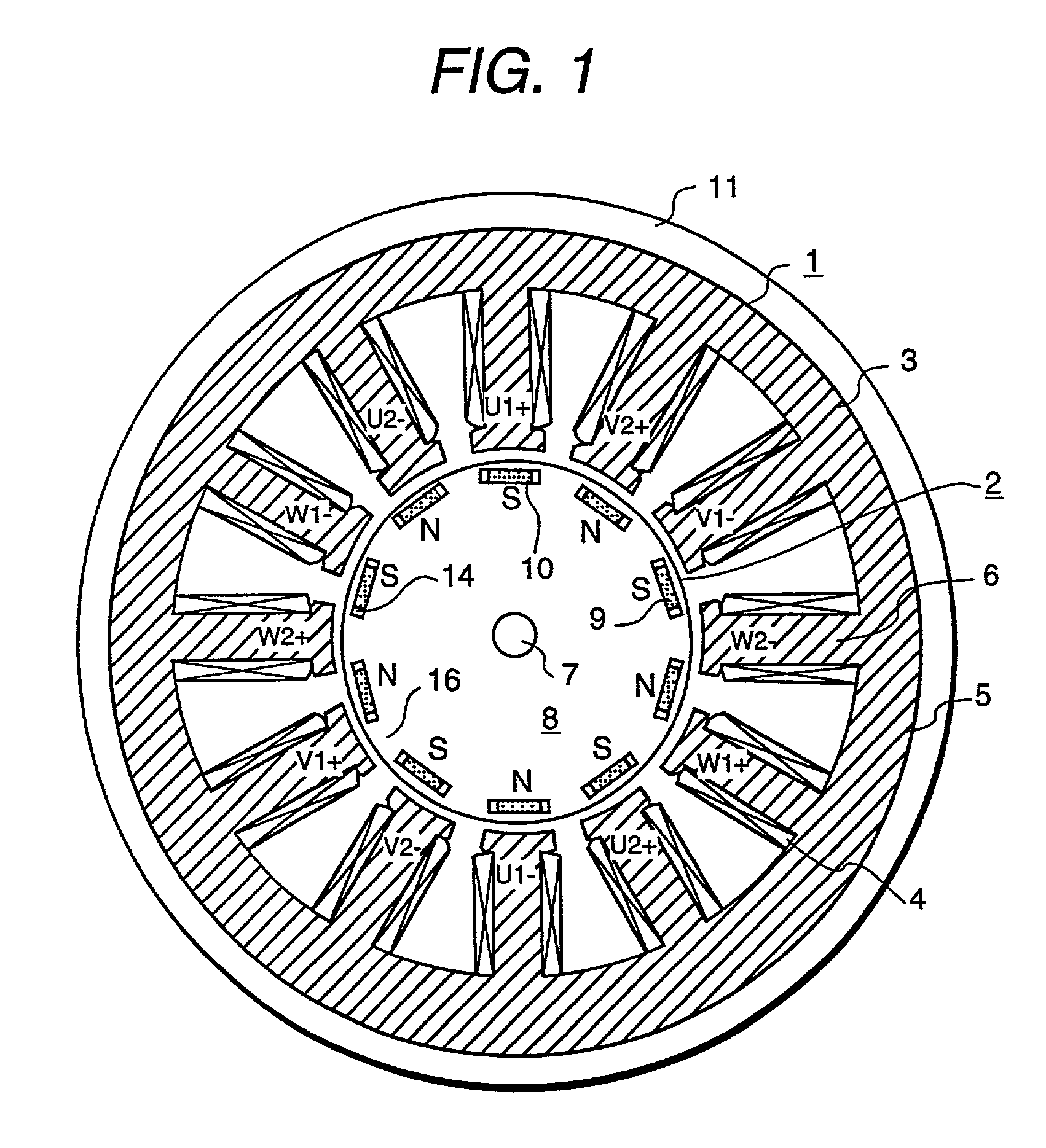
[0065] FIG. 1 is a peripheral direction cross-sectional view showing one embodiment of an inner rotor type concentrated winding stator structure permanent magnet electric rotating machine according to the present invention.

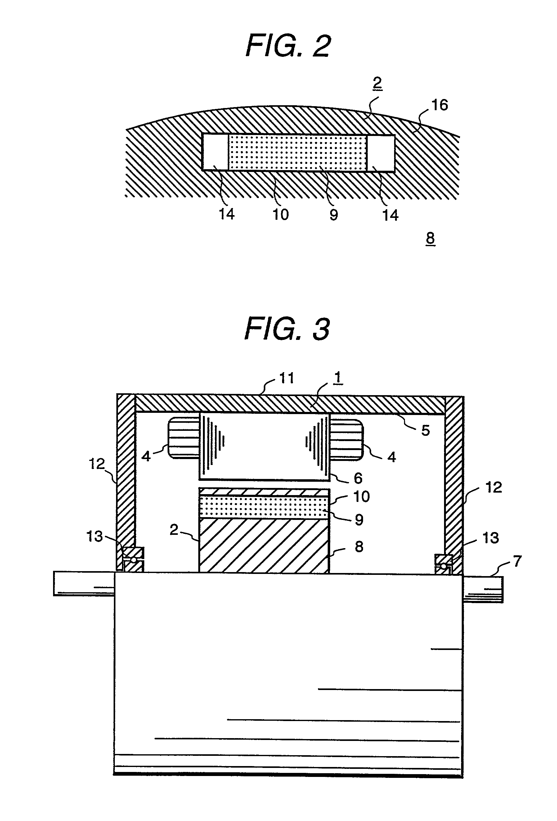
[0066] A permanent magnet electric rotating machine is constituted by a stator 1 and a rotor 2, and the stator 1 and the rotor 2 are arranged with a rotation air gap each other as shown in figure.

[0067] The stator 1 comprises a stator iron core 3 and a stator winding 4. The stator iron core 3 comprises a core portion 5 and a stator salient pole portion 6. In the core portion 5, a magnetic circuit is formed so to pass a magnetic flux to the stator salient pole portion 6. In this stator sa...


PUM


Abstract

A magnetic gap is provided between permanent magnet of a rotor and an auxiliary magnetic pole portion which is adjacently arranged to the permanent magnet to a peripheral direction. A change in a magnetic flux density distribution of a surface of the rotor is performed moderately and a cogging torque and a torque pulsation are restrained. By obtaining a reluctance torque according to the auxiliary magnetic pole, a permanent magnet electric rotating machine in which the cogging torque and the torque pulsation are restrained can be obtained and further an electromotive vehicle having the permanent magnet electric rotating machine can be provided.

Description

[0001] 1. Technical Field[0002] The present invention relates to a permanent magnet electric rotating machine and an electromotive vehicle using a permanent magnet electric rotating machine and in particularly to a permanent magnet electric rotating machine in which permanent magnets are used as a magnetic flux generating means and an electromotive vehicle such as an electric vehicle using a permanent magnet electric rotating machine.[0003] 2. Prior Arts[0004] Up to now as one kind of a electric rotating machine, a permanent magnet electric rotating machine has used, in which permanent magnets of the permanent magnet electric rotating machine are used as a magnetic field generating means for a rotor.[0005] As a conventional permanent magnet electric rotating machine, there is a surface magnet structure permanent magnet electric rotating machine, namely plural permanent magnets of the permanent magnet electric rotating machine are arranged in parallel and fixed on a surface of a roto...

Claims


Application Information

Patent Timeline
Patent Type & Authority Applications(United States)
IPC IPC(8): H02K1/27
CPCH02K1/276H02K29/03
Inventor TAJIMA, FUMIOMATSUNOBU, YUTAKAKAWAMATA, SHOUICHISHIBUKAWA, SUETAROKOIZUMI, OSAMUODA, KEIJI
Owner HITACHI LTD
Why Eureka
Try Eureka