
Fixed support for welding

A technology for fixing supports and columns, applied in welding equipment, auxiliary welding equipment, welding/cutting auxiliary equipment, etc., can solve the problems of inflexible structure and inconvenient use, and achieve simple structure, good practicability, and welding Flexible and convenient effects

Inactive Publication Date: 2019-05-03
伍兴平
View PDF0 Cites 0 Cited by
  • Summary
  • Abstract
  • Description
  • Claims
  • Application Information

AI Technical Summary

Problems solved by technology

[0002] Welding has become an essential process for the connection between structures. When welding the workpiece, it needs to be fixed and the welding is completed. However, the structure of the existing welding device is inflexible and inconvenient to use.

Method used


Image

  • Fixed support for welding
  • Fixed support for welding

Examples


Embodiment Construction

[0011] The embodiments of the present invention will be further described below in conjunction with the accompanying drawings.

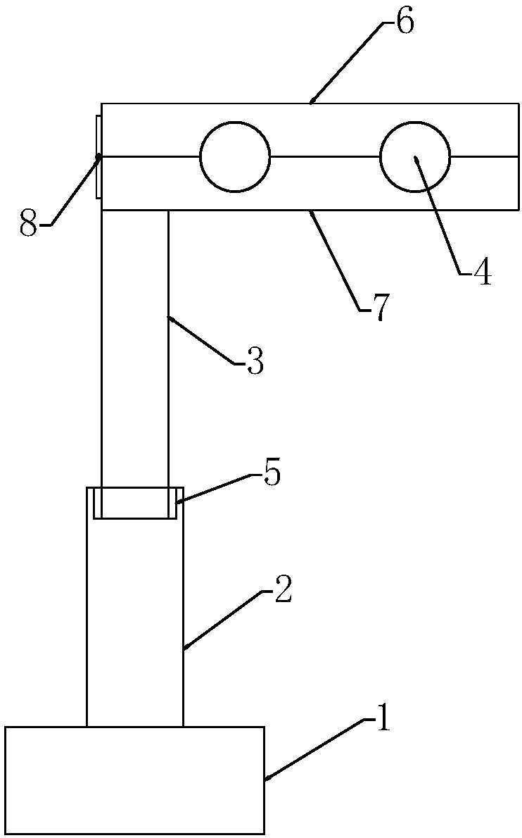
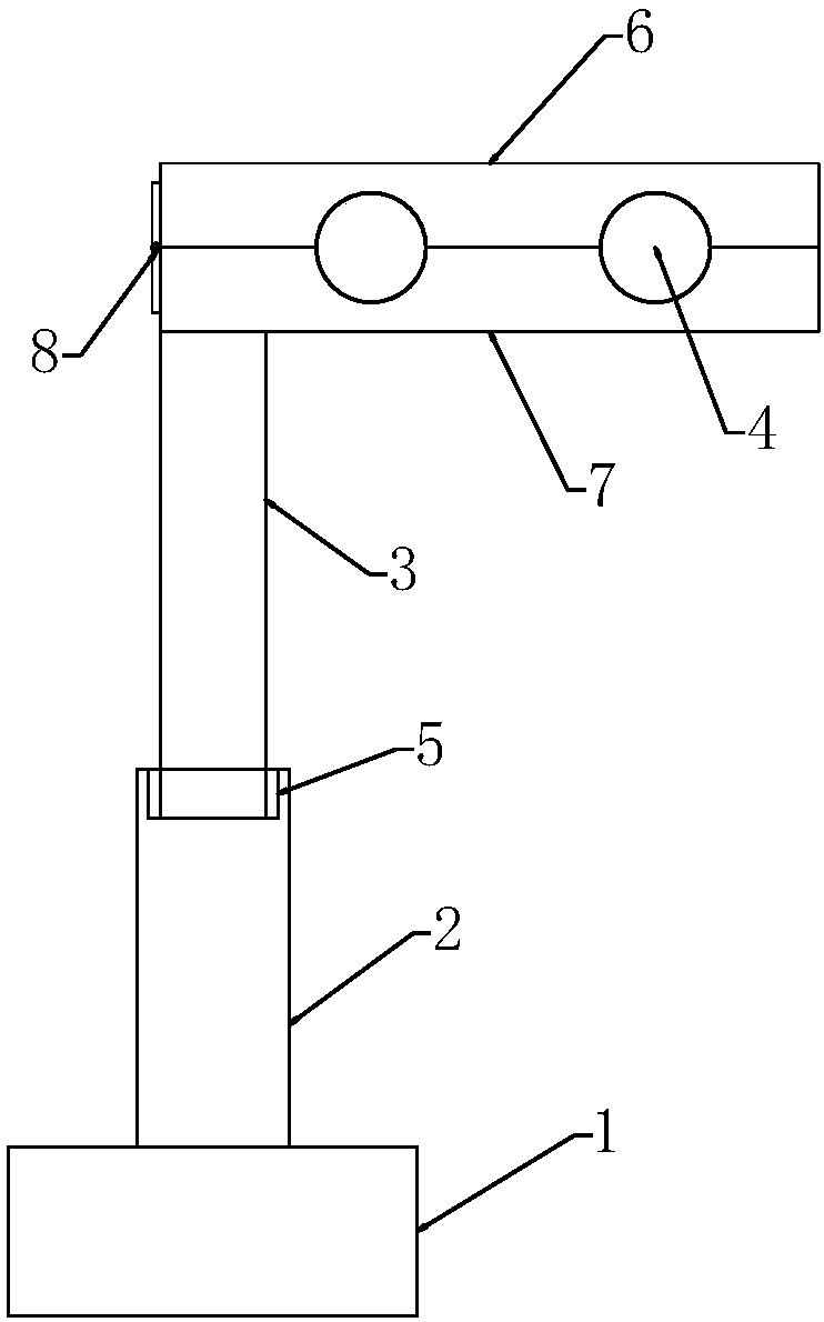
[0012] Such as figure 1 As shown, a fixed support for welding provided in this embodiment includes a base 1, a fixed column 2 is provided on the base 1, a rotating column 3 is provided on the fixed column 2, and the rotating column 3 is connected with the fixed column. The column 2 is rotationally connected. Specifically, a groove can be provided at the center of the top of the fixed column 2, and a rolling bearing 5 is arranged in the groove. The outer ring of the rolling bearing 5 is fixedly connected with the inner wall of the groove. The rolling bearing The inner ring of 5 is fixedly connected with the outer wall of the rotating column 3, so as to realize the rotating connection between the rotating column 3 and the fixed column 2.

[0013] The top of the rotating column 3 is provided with a clamp assembly, and the clamp assembly is provided wit...


PUM


Abstract

The invention relates to the technical field of welding, in particular to a fixed support for welding. The fixed support for welding comprises a base, wherein a fixed pillar is arranged on the base; arotary pillar is arranged on the fixed pillar and is rotatably connected with the fixed pillar; a fixture assembly is arranged on the top part of the rotary pillar; and a fixed through hole is formedin the fixture assembly. During welding, the device can be used for rotating the fixture assembly, so that the device is flexible and convenient to weld, has good practicability, and is simple in structure at the same time.

Description

technical field [0001] The invention relates to the field of welding technology, in particular to a fixed support for welding. Background technique [0002] Welding has become an essential process for connecting structures. When welding workpieces, they need to be fixed and welded. However, the structure of existing welding devices is inflexible and inconvenient to use. Contents of the invention [0003] The object of the present invention is to provide a fixed support for welding with simple structure and convenient use. [0004] The technical solution adopted in the present invention is: a fixed support for welding, including a base, the base is provided with a fixed column, the fixed column is provided with a rotating column, and the rotating column is rotatably connected with the fixed column. A clamp assembly is arranged on the top of the rotating column, and a fixing through hole is arranged in the clamp assembly. [0005] The above-mentioned fixed support for weld...

Claims


Application Information

Patent Timeline
Patent Type & Authority Applications(China)
IPC IPC(8): B23K37/04
Inventor 伍兴平
Owner 伍兴平
Learn More