A circuit breaker drawer

A drawer seat, circuit breaker technology, applied in the direction of pull-out switch cabinets, electrical components, switch devices, etc., can solve the problems of high cost, inconvenient installation and maintenance, complicated structure, etc., and achieve long service life, simple structure, and easy installation. handy effect

Active Publication Date: 2020-04-17
CHANGSHU SWITCHGEAR MFG CO LTD (FORMER CHANGSHU SWITCHGEAR PLANT)
View PDF7 Cites 0 Cited by
  • Summary
  • Abstract
  • Description
  • Claims
  • Application Information

AI Technical Summary

Problems solved by technology

Although this structure has the function of "connecting" position locking, it requires additional locking parts to achieve locking, which has high cost, and the structure is cumbersome, and installation and maintenance are inconvenient

Method used


Image

  • A circuit breaker drawer
  • A circuit breaker drawer
  • A circuit breaker drawer

Examples


no. 3 example

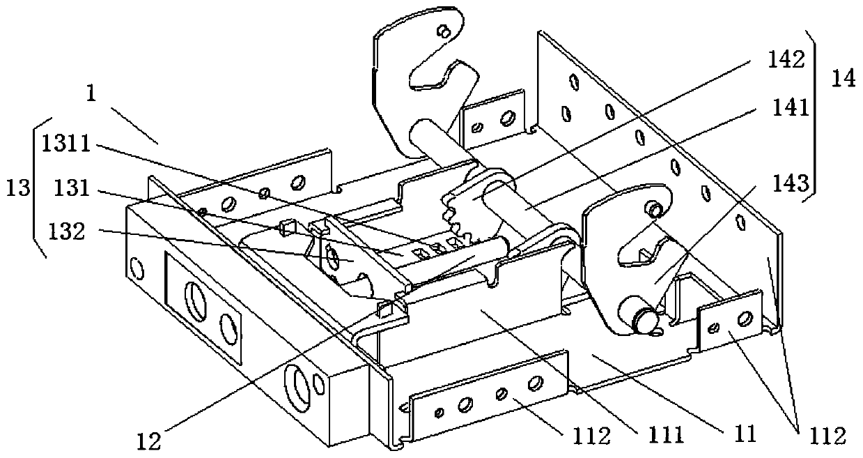
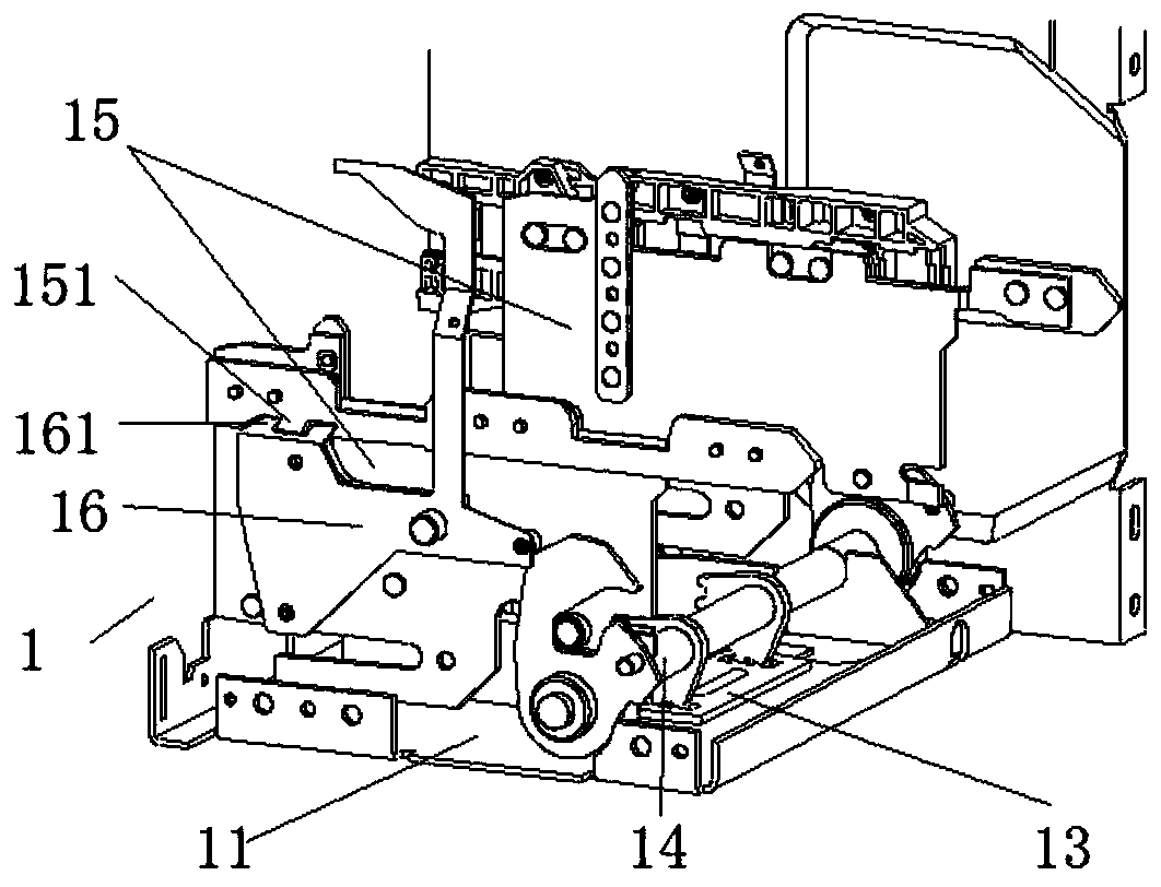
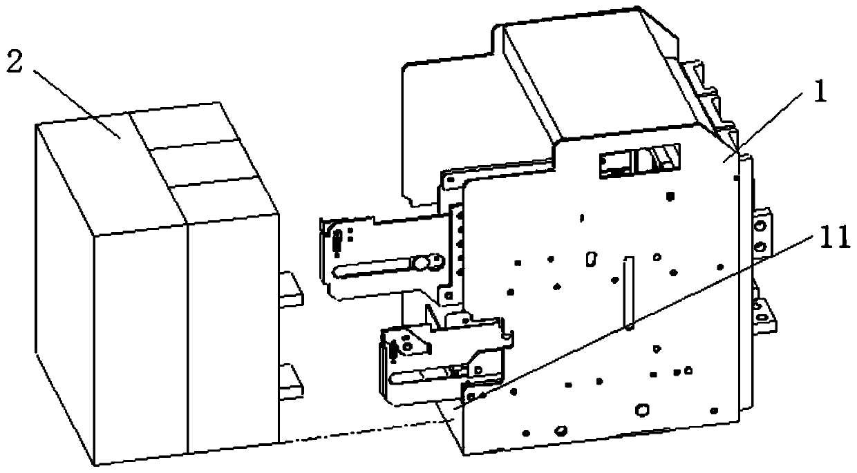
[0051] The third embodiment is the change realized on the basis of the first embodiment. The scheme is: first, in this embodiment, the shaft assembly 14 also includes a traction plate, and the traction plate is fixed on the shaft assembly 14 on the shaft 141, the traction plate is used to drive the movement of the guide plate 15; the second type, the shaft assembly 14 also includes a traction plate, the traction plate is fixed on the shaft 141 of the shaft assembly 14, and the traction plate is used to drive the circuit breaker The movement of the device body 2. In the first embodiment, the locking plate 143 of the rotating shaft assembly 14 has two functions. One function is to cooperate with the first round roller 152 to lock the circuit breaker body 2 at the "connected" position. Another function is to drag the circuit breaker body 2 to move during the movement of the circuit breaker body 2 , but in the third embodiment, these two functions are realized by separate componen...

no. 4 example

[0052] The fourth embodiment is a change realized on the basis of the second embodiment. The solution is: first, in this embodiment, the shaft assembly 14 also includes a traction plate, and the traction plate is fixed on the shaft assembly. 14 on the shaft 141, the traction plate is used to drive the movement of the guide plate 15; the second type, the shaft assembly 14 also includes a traction plate, the traction plate is fixed on the shaft 141 of the shaft assembly 14, and the traction plate is used to drive the circuit breaker The movement of the device body 2. The difference from the third embodiment lies in the specific solution, that is, a traction groove 1431 is provided on the traction plate. And the locking plate 143 is provided with a first locking arc segment 1432 and a second locking arc segment 1433 .


PUM


Abstract

A circuit breaker drawer seat is provided. The circuit breaker comprises a circuit breaker body and a drawer seat matching the circuit breaker body. The drawer seat comprises a rotating shaft assemblyand a pair of guiding plates. The rotating shaft assembly is rotatably disposed on the drawer seat. The pair of guiding plates are slidably disposed on both sides of the drawer seat respectively. Therotating shaft assembly rotates and then moves the circuit breaker body on the guiding plates through the pair of guiding plates. The circuit breaker drawer seat is characterized in that the rotatingshaft assembly comprises a pair of locking plates; each locking plate comprises a first locking arc segment; the arc center of the first locking arc segment is a rotation center of the locking plate;the pair of guiding plates are provided with first circular rollers that move synchronously with the guiding plates and fit with the first locking arc segments; when the circuit breaker body is at aconnection position, the first circular rollers are attached to the first locking arc segments on the corresponding locking plates to prevent the circuit breaker body from moving from the connection position to a test position. The circuit breaker drawer seat has the advantages of reliable locking, simple structure, low cost, convenient installation and a long service life.

Description

technical field [0001] The invention belongs to the technical field of low-voltage electrical appliances, and in particular relates to a circuit breaker drawer seat. Background technique [0002] Due to the convenience of inspection and maintenance, the withdrawable universal circuit breaker is widely used. The withdrawable universal circuit breaker is divided into two parts: the circuit breaker body and the drawer base. The drawer base is directly connected to the external power supply. The circuit breaker body can be pushed or pulled out in the drawer base. During actual use, the withdrawable circuit breaker may bear a large short-circuit fault current, and the huge electric force makes the circuit breaker body tend to be pushed out. At this time, if there is no reliable locking structure inside the circuit breaker, the circuit breaker The main body may be pushed out of the drawer seat, causing the internal busbar and bridge contacts to slip off, causing malignant faults ...

Claims


Application Information

Patent Timeline
Patent Type & Authority Patents(China)
IPC IPC(8): H02B11/133H02B11/173
Inventor 陈斌钱锦丰朱永清
Owner CHANGSHU SWITCHGEAR MFG CO LTD (FORMER CHANGSHU SWITCHGEAR PLANT)
Why Eureka
Try Eureka