
Lifting device

A lifting device and lifting component technology, applied in the direction of lifting device, lifting frame, etc., can solve the problems of large damage to fasteners, heavy overall weight, inconvenient carrying and handling, etc., and achieve the effect of improving applicability and convenient transportation.

Pending Publication Date: 2020-09-11
NINGBO TIANHONG POWER APPLIANCE +1
View PDF2 Cites 2 Cited by
  • Summary
  • Abstract
  • Description
  • Claims
  • Application Information

AI Technical Summary

Problems solved by technology

However, in the follow-up use, the inventors found that several lifting devices in the past still had the following problems: (1) the volume was large, the overall weight was heavy, and it was inconvenient to carry and carry when working outdoors; The locking wheel assembly is essential for the limit along the horizontal direction, but before installing the mounting bracket to the guide rail, the locking wheel assembly must be removed first, then the mounting bracket is close to the guide rail, and finally the locking wheel assembly is installed on the The horizontal limit is realized on the outside of the guide rail; the loading and unloading process is time-consuming and laborious, and frequent loading and unloading will cause great damage to the fasteners, which are prone to loosening and pose a safety hazard; (3) there are still defects in function, especially in terms of intelligent control.

Method used


Image

  • Lifting device
  • Lifting device
  • Lifting device

Examples


Embodiment Construction

[0058] The following description serves to disclose the present invention to enable those skilled in the art to carry out the present invention. The preferred embodiments described below are only examples, and those skilled in the art can devise other obvious variations.

[0059] In the description of the present invention, it should be noted that for orientation words, such as the term "center", "horizontal", "longitudinal", "length", "width", "thickness", "upper", "lower" , "Front", "Back", "Left", "Right", "Vertical", "Horizontal", "Top", "Bottom", "Inner", "Outer", "Clockwise", "Counterclockwise " and other indication orientations and positional relationships are based on the orientations or positional relationships shown in the drawings, and are only for the convenience of describing the present invention and simplifying the description, rather than indicating or implying that the device or element referred to must have a specific orientation, or in a specific orientation...


PUM


Abstract

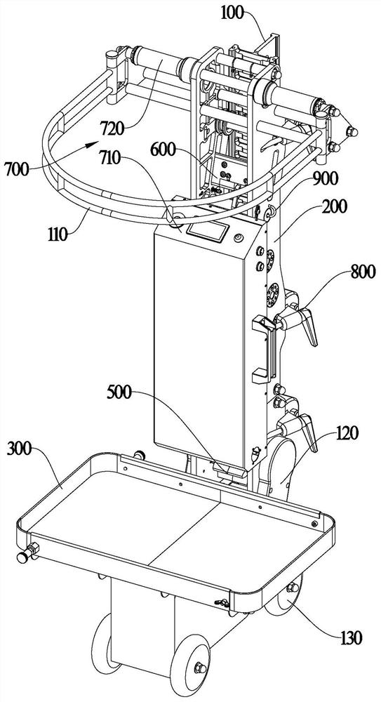
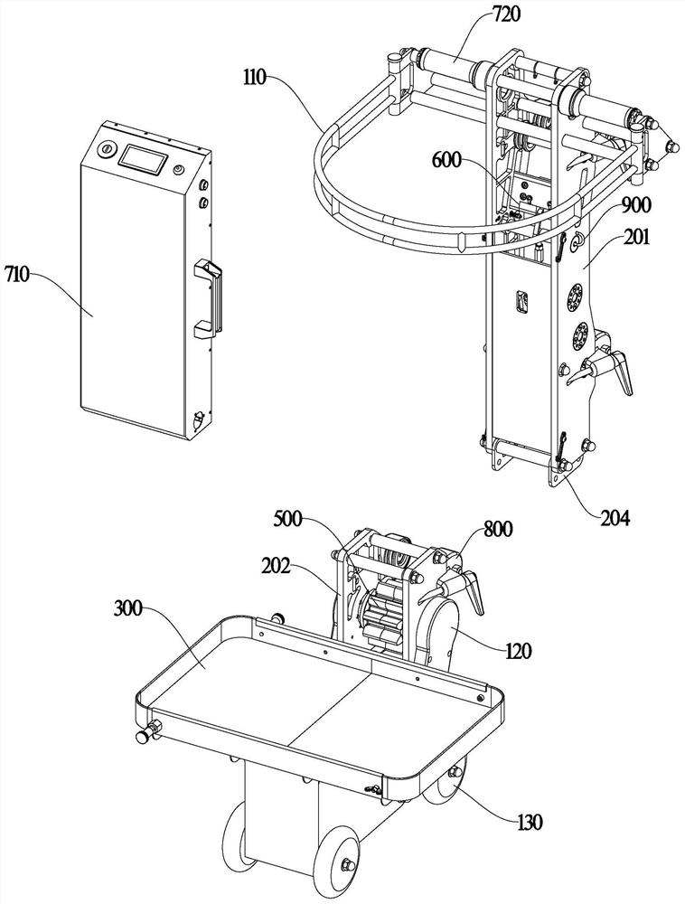
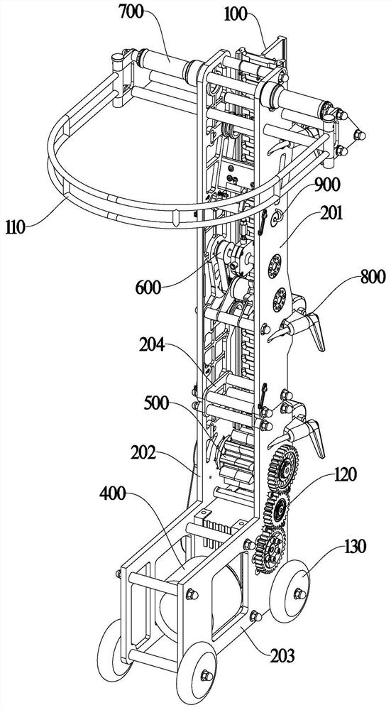
The invention provides a lifting device. The lifting device comprises a guide rail, a mounting rack, a loading platform, a power assembly, a lifting assembly, a locking assembly, a control assembly and a roller assembly; the roller assembly comprises fixed rollers and movable rollers, wherein multiple groups of the fixed rollers and the movable rollers are arranged on the mounting rack at intervals along the vertical direction; the fixed rollers are rotatably arranged at the inner side of the mounting rack, and are suitable for abutting against the front side of the guide rail; the movable rollers are arranged at the outer side of the mounting rack, and are suitable for abutting against the rear side of the guide rail; the fixed rollers and the movable rollers cooperate with each other torealize the horizontal limit and vertical movement of the mounting rack relative to the guide rail; and each movable roller comprises a rotating rod, a sliding block, a wheel body and a locking element. The lifting device provided by the invention has the advantages of being in modularized split arrangement, convenient in assembly and disassembly, safe and reliable, and stable in operation.

Description

technical field [0001] The invention relates to tool equipment, in particular to a lifting device. Background technique [0002] Lifting equipment is a device that enables people or things to move back and forth between low and high places. The important indicators of lifting equipment are: 1. Safety; 2. Detachability; 3. Has the function of crisis relief and escape. [0003] At present, the common lifting mechanisms include civil elevators and building elevators. Civilian elevators have high requirements for supporting facilities, and generally cannot be used for outdoor operations; cables are used for lifting, and cable breakage is prone to fall accidents. In addition, power failure during operation is not conducive to escape. Construction lifts are suitable for outdoor use, but steel pipe supports are required, making the construction relatively complex and costly. At the same time, construction lifts are lifted by cables, which are prone to fall accidents if the cables ...

Claims


Application Information

Patent Timeline
Patent Type & Authority Applications(China)
IPC IPC(8): B66F7/00B66F7/28
CPCB66F7/00B66F7/28
Inventor 赖建防吕伟宏李善东林江南陈云任典跃
Owner NINGBO TIANHONG POWER APPLIANCE
Learn More