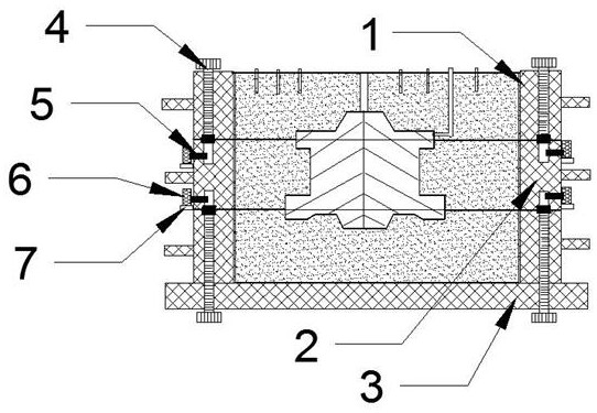
A three-box sand mold for metal casting

A technology of metal casting and sand molding, which is applied in the field of three-box sand molding for metal casting, and can solve problems such as defects, deformation of bolts and screw holes, erosion of molten metal, or vibration offset.

Active Publication Date: 2020-11-03
和县华顺铸造有限公司
View PDF7 Cites 0 Cited by
  • Summary
  • Abstract
  • Description
  • Claims
  • Application Information

AI Technical Summary

Problems solved by technology

[0004] During the sand casting process, the model needs to be assembled and fixed. The stable assembly of the sand mold determines the accuracy of the processed pattern. If the structure of the sand mold cannot be assembled correctly, stably, and firmly, it may be due to its own weight, the erosion of molten metal, or vibration. Offset occurs, resulting in pattern distortion or structural defects
Conventional molding fixtures include bolts and buckles, etc. The bolts have a good fastening effect and are resistant to vibration. They can still remain stable after shocking during the sand tightening process. However, due to the large amount of sand released in the casting process Heat, heat will cause deformation between the bolt and the screw hole, and eventually cause the bolt to lock, which will cause difficulties in dismantling the sand mold and demolding the part blank
The heat-resistant and anti-deformation effect of the buckle is good, and the problem of locking is not easy to occur; but the stability of the fastening effect of the buckle is relatively poor, and it is easy to loosen in a vibration environment, which affects the compaction effect of the sand mold and the casting parts machining accuracy

Method used


Image

  • A three-box sand mold for metal casting
  • A three-box sand mold for metal casting
  • A three-box sand mold for metal casting

Examples


Embodiment Construction

[0030] In order to make the purpose, technical solutions and advantages of the embodiments of the present invention more clear, the technical solutions in the embodiments of the present invention will be clearly and completely described below in conjunction with the drawings in the embodiments of the present invention.

[0031] In the description of the present invention, it should be noted that unless otherwise specified, the meaning of "plurality" is two or more; the terms "upper", "lower", "left", "right", "inner ", "outside", "front end", "rear end", "top", "bottom" and other indicated orientations or positional relationships are based on the orientations or positional relationships shown in the drawings, and are only for the convenience of describing the present invention and simplifying the Describes, but does not indicate or imply that the device or element referred to must have a specific orientation, be constructed in a specific orientation, and operate in a specific o...


PUM


Abstract

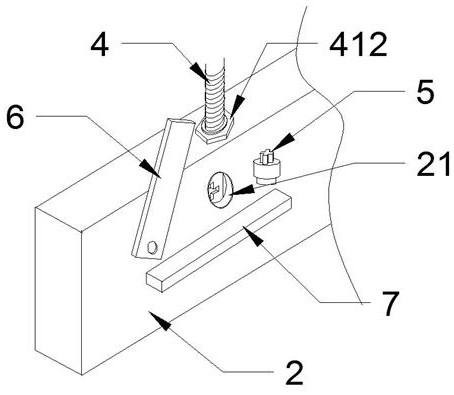
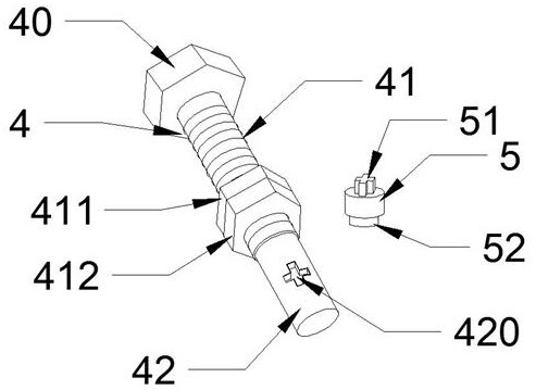
The invention belongs to the technical field of metal casting processing, and particularly relates to a three-box sand mold for metal casting. The three-box sand mold comprises an upper sand mold body, a middle sand mold body and a lower sand mold body, wherein screw holes for fastening are formed in the upper sand mold body and the lower sand mold body, inner threads are arranged in the screw holes of the upper sand mold body and the lower sand mold body, corresponding non-threaded through holes are formed in the upper part and the lower part of the middle sand mold body, the side surfaces ofthe through holes in the middle sand mold body are provided with groove holes, the lower edges of the groove holes are provided with transverse baffles which protrudes outwards, the outer walls, at the groove holes, of the sand mold body at are further provided with baffles capable of rotating along the surface of the sand mold body, the lower sections of bolts in the screw holes are non-threadedthrough rod section, the upper parts of the bolts are threaded sections, openings are formed in the positions, corresponding to the groove holes, of the through rod sections, hole plugs are arrangedat the position of the groove holes, plug heads matched with the upper openings of the bolts are arranged at the front ends of the hole plugs, and the heights of the hole plugs protrudes out of the outer surface of the sand mold body. The anti-vibration and heat-resistant anti-deformation effect of the sand mold is better, the bolts cannot be locked, and mold striping is easier to perform.

Description

technical field [0001] The invention belongs to the technical field of metal casting, and in particular relates to a three-box sand mold for metal casting. Background technique [0002] Casting is a method of casting liquid metal into a casting cavity suitable for the shape of the part, and then cooling and solidifying it to obtain parts or blanks; it is one of the most commonly used processing methods for metal parts with complex structures. The mold materials used in casting are mainly sand, metal and ceramics; sand molds have become the most important mold materials because of their advantages of easy processing, easy demoulding, and low cost. [0003] According to different morphological characteristics, commonly used casting sand molds include different types such as two-box sand molds, three-box sand molds, pit sand molds, and core sand molds. Two-box sand molds are the simplest sand mold structure and can be applied to casting parts of most structures. , it is very c...

Claims


Application Information

Patent Timeline
Patent Type & Authority Patents(China)
IPC IPC(8): B22C21/02B22C21/08
CPCB22C21/02B22C21/08
Inventor 刘榄
Owner 和县华顺铸造有限公司
Why Eureka
Try Eureka