Single-shaft turbo compressor

A turbo compressor, single-shaft technology, used in mechanical equipment, non-variable displacement pumps, non-displacement pumps, etc.

Active Publication Date: 2019-05-03
SIEMENS ENERGY GLOBAL GMBH & CO KG
View PDF17 Cites 0 Cited by
  • Summary
  • Abstract
  • Description
  • Claims
  • Application Information

AI Technical Summary

Problems solved by technology

In addition to the problems which are only superficially outlined here, other difficulties arise during assembly, for example when the sealing element between the outer housing and the insert is slightly damaged during assembly.
[0014] A further series of problems of the prior art arise due to the connections, for example connecting the shaft seal to supply or removal lines for eg sealing gas or extraction, which often also have to be correspondingly accessible. Separately constructed so that assembly and disassembly can occur without disrupting the interface

Method used


Image

  • Single-shaft turbo compressor
  • Single-shaft turbo compressor
  • Single-shaft turbo compressor

Examples


Embodiment Construction

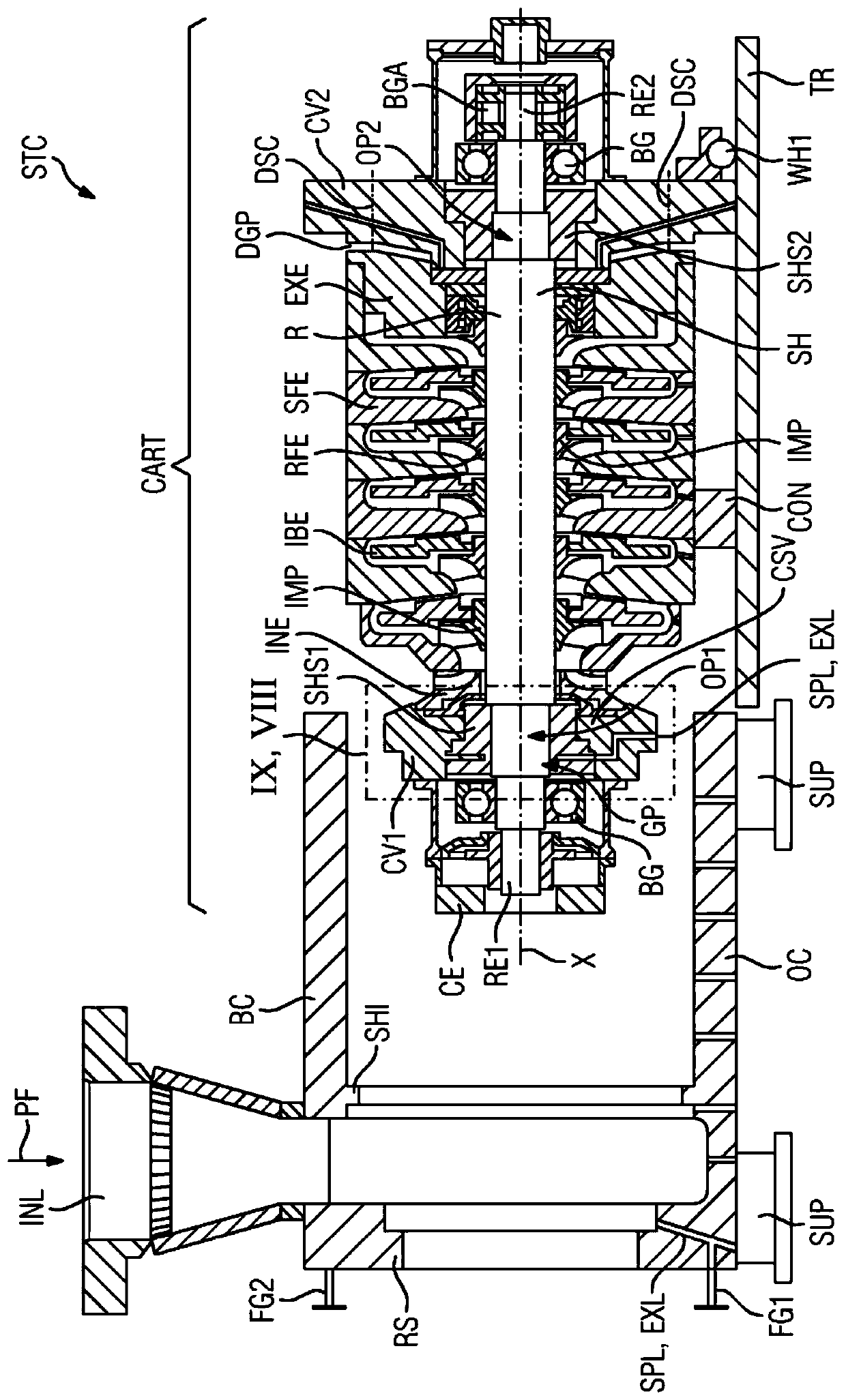
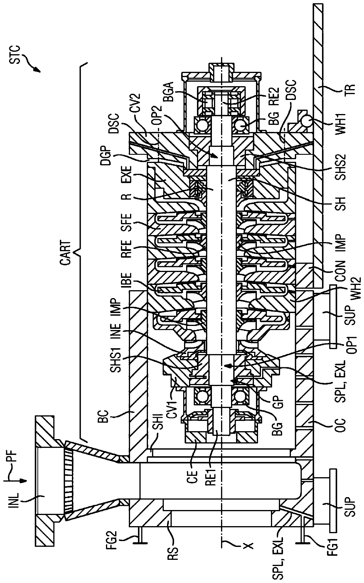
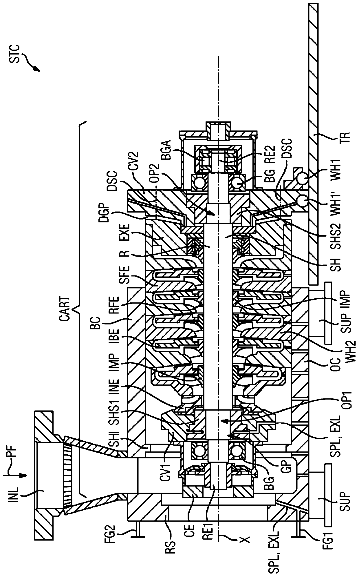
[0033] Figures 1 to 8 The single-shaft turbo compressors STC are each shown schematically in longitudinal section.

[0034] The single-shaft turbo compressor STC comprises a rotor R extending along an axis X, said rotor having a shaft SH and an impeller IMP (referenced only as an example) arranged on the shaft SH. The outer housing OC is provided with a first end-side cover CV1 and a second end-side cover CV2 in order to seal off the cover part BC of the outer housing OC. The covers CV1 , CV2 have openings OP1 , OP2 through which the respective ends of the rotor R extend. The rotor R is supported radially by means of bearings BG or radial bearings, wherein the axial bearings BGA hold the rotor R in a defined axial position.

[0035] The cover part BC is erected on the foot unit SUP along the axis X in a horizontally extending axial direction. The cover part BC has an inflow INL, wherein the existing outflow is not visible in the schematic representation. The process fluid...


PUM


Abstract

The invention relates to a single-shaft turbo compressor (STC) comprising a rotor (R) extending along an axis (X), an outer housing (OC), static flow fittings (SFE), bearings (BG) for supporting the rotor (R), and at least one first shaft seal (SHS1), wherein the rotor (R) has a shaft (SH) and an impeller (IMP) arranged on the shaft (SH), wherein the static flow fittings (SFE) have supply elements(INE), intermediate elements (IBE) and discharge elements (EXE), and wherein the outer housing (OC) has a casing part (BC) that is open at the end on both sides. According to the invention, a first cover (CV1) of the outer housing (OC) is connected to a first shaft seal (SHS1), wherein supply lines (SPL) and discharge lines (EXL) of the first shaft seal (SHS1) are provided extending through the first cover (CV1) into a wall thickness of the casing part (BC) adjacent to the first cover (CV1).

Description

technical field [0001] The invention relates to a single-shaft turbo compressor, comprising: [0002] - a rotor extending along the axis, [0003] - outer shell, [0004] - bearings for supporting the rotor, [0005] - at least one first shaft seal, [0006] The rotor has a shaft and an impeller arranged on the shaft, wherein the stationary flow insert comprises an inlet element, an intermediate guide element and an outlet element, wherein the outer housing has a first cover on the end side, a second cover on the end side and along the A cover part that is not divided in the circumferential direction and that extends tubularly in the axial direction and is open on both ends, wherein the outer housing is designed such that the first cover extends radially outward from the The interior of the outer housing rests against a radially inwardly protruding shoulder extending in the circumferential direction, wherein the first rotor end is guided through a first axial opening of th...

Claims


Application Information

Patent Timeline
Patent Type & Authority Applications(China)
IPC IPC(8): F04D17/12F04D29/10F04D29/42F04D29/62
CPCF04D17/125F04D29/10F04D29/4206F04D29/624F04D1/08F04D29/044F04D29/054F04D29/056F04D29/083F04D29/102F04D29/122F04D29/603
Inventor 弗雷德里克·希尔根贝格迪特尔·纳斯
Owner SIEMENS ENERGY GLOBAL GMBH & CO KG
Why Eureka
Try Eureka