
A method for motion planning of a mechanical arm, a mechanical arm, and a robot

A motion planning and robotic arm technology, applied in the directions of manipulators, program-controlled manipulators, instruments, etc., can solve the problems of robot damage, jitter, affecting the effect of robot motion, etc., and achieve the effect of continuous and stable motion and preventing jitter.

Active Publication Date: 2022-03-11
CLOUDMINDS SHANGHAI ROBOTICS CO LTD
View PDF6 Cites 0 Cited by
  • Summary
  • Abstract
  • Description
  • Claims
  • Application Information

AI Technical Summary

Problems solved by technology

For a general six-degree-of-freedom serial robot, the path planning process is relatively mature, because the number of inverse kinematics solutions for a six-degree-of-freedom robot is limited, and the current moment only needs to select a group of joints with the smallest angle difference from the previous moment. The angle value is enough, but for a higher-dimensional robot, such as a seven-degree-of-freedom robot, each end pose corresponds to an infinite number of joint values, so it is difficult to choose an optimal set of solutions to ensure that the angle and angular velocity are continuous during motion, and Discontinuous joint angle changes will cause shaking of the robot movement, seriously affecting the robot movement effect and easily causing damage to the robot

Method used


Image

  • A method for motion planning of a mechanical arm, a mechanical arm, and a robot
  • A method for motion planning of a mechanical arm, a mechanical arm, and a robot
  • A method for motion planning of a mechanical arm, a mechanical arm, and a robot

Examples


Embodiment Construction

[0031] Exemplary embodiments of the present disclosure will be described in more detail below with reference to the accompanying drawings. Although exemplary embodiments of the present disclosure are shown in the drawings, it should be understood that the present disclosure may be embodied in various forms and should not be limited by the embodiments set forth herein. Rather, these embodiments are provided for more thorough understanding of the present disclosure and to fully convey the scope of the present disclosure to those skilled in the art.

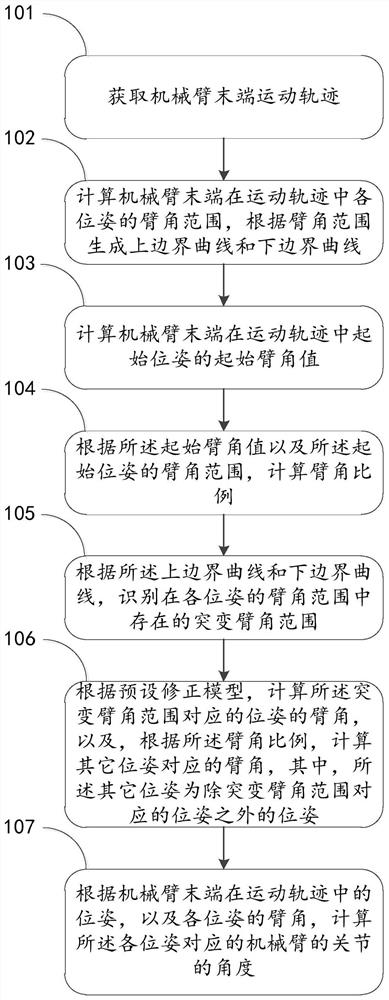
[0032] see figure 1 , figure 1 It is a flow chart of an embodiment of a method for manipulator motion planning in the present invention, and the method includes:

[0033] Step 101: Obtain the motion trajectory of the end of the mechanical arm;

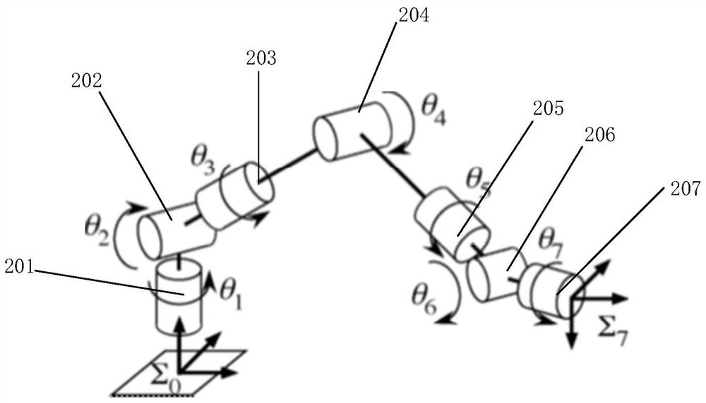
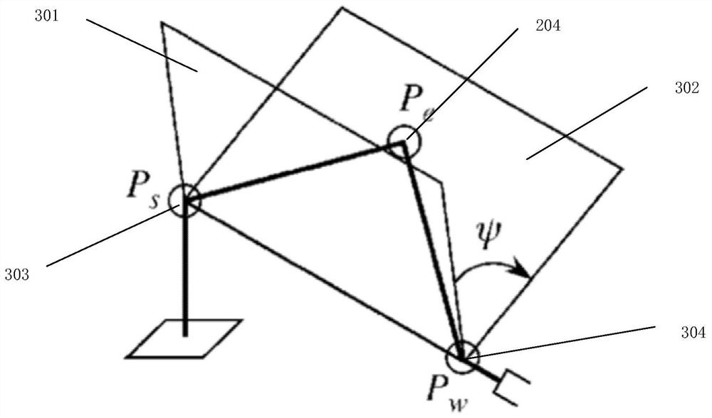
[0034] The robotic arm is composed of multiple joints, and the rotation of the robotic arm can be realized through the linkage between the joints. The arm angle refers to the angle at wh...


PUM


Abstract

The embodiment of the present invention relates to the technical field of mechanical arm control, and in particular discloses a method for motion planning of a mechanical arm, a mechanical arm, and a robot. The arm angle value, and generate the upper boundary curve and the lower boundary curve according to the arm angle range and identify the sudden arm angle range existing in the arm angle range of each posture, and calculate according to the initial arm angle value and the arm angle range of the initial pose Arm angle ratio, according to the preset correction model, calculate the arm angle of the pose corresponding to the mutation arm angle range, calculate the arm angle corresponding to other poses according to the arm angle ratio, and finally according to the pose of the end of the robot arm in the motion track, And the arm angles of each posture, calculate the angle of the manipulator joint corresponding to each posture. Through the above method, the embodiment of the present invention can make the joint rotation angle of the mechanical arm continuous during the movement, and can ensure the continuous and stable movement of the mechanical arm.

Description

technical field [0001] Embodiments of the present invention relate to the technical field of robotic arm control technology, and in particular, relate to a method for motion planning of a robotic arm, a robotic arm, and a robot. Background technique [0002] A robot refers to a machine that simulates human behavior or thought and simulates other living things. With the development of artificial intelligence technology and mechanical design technology, the flexibility of robots is getting higher and higher, and the degree of intelligence is getting higher and higher, which makes the application range of robots more and more extensive. [0003] In the process of realizing the present invention, the inventors of the present invention found that the motion planning of the manipulator has always been the focus of research in robotics. Generally, the poses of the starting point and the end point are known for this type of problem. How to choose a complete and optimal Path is the ...

Claims


Application Information

Patent Timeline
Patent Type & Authority Patents(China)
IPC IPC(8): B25J9/16
CPCB25J9/1664G05B2219/40495B25J9/1651B25J9/163
Inventor 王天昊徐慎华
Owner CLOUDMINDS SHANGHAI ROBOTICS CO LTD
Learn More