Pneumatic tire

A technology for pneumatic tires and tread parts, applied in tire parts, tire tread/tread pattern, transportation and packaging, etc., can solve the problem of insufficient retention strength, and achieve the effect of improving driving performance

Inactive Publication Date: 2019-05-14
TOYO TIRE & RUBBER CO LTD
View PDF5 Cites 0 Cited by
  • Summary
  • Abstract
  • Description
  • Claims
  • Application Information

AI Technical Summary

Problems solved by technology

[0003] However, according to the above-mentioned conventional pneumatic tire, the recesses having almost the same depth as the nail holes are arranged nearby, so that the holding strength of the nail holes for holding the studs is insufficient.

Method used


Image

  • Pneumatic tire
  • Pneumatic tire
  • Pneumatic tire

Examples


Embodiment Construction

[0023] Embodiments of the present invention will be described below with reference to the accompanying drawings. In addition, the following description is merely an illustration in nature, and is not intended to limit the present invention, its application, or its use.

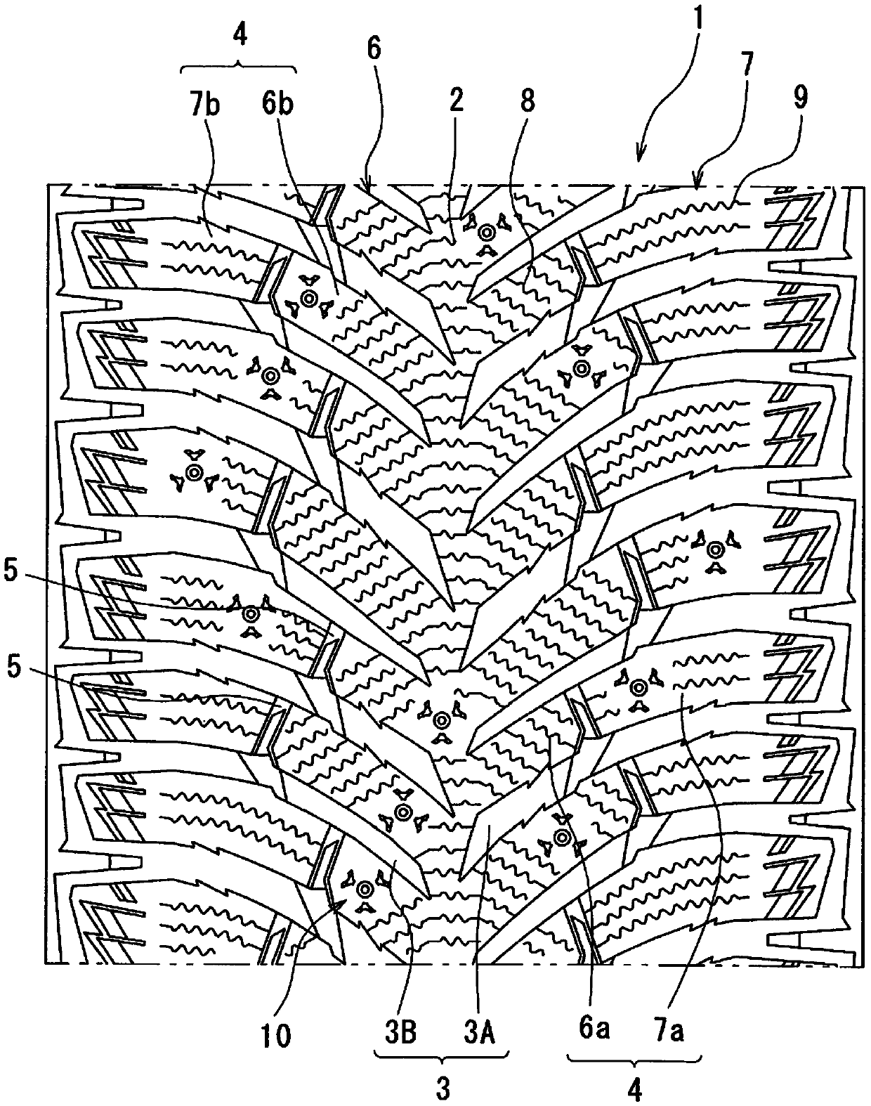
[0024] figure 1 It is a partially developed view of the tread portion 1 of the pneumatic tire according to the present embodiment. In the tread portion 1, a center rib 2 is formed at the center in the tire width direction. Extending from the center rib 2 toward both sides in the tire width direction are inclined blocks 4 defined by the inclined grooves 3 . Accordingly, the inclined blocks 4 are arranged at predetermined intervals in the tire circumferential direction.

[0025] The inclined groove 3 is composed of a first inclined groove 3A having a wide width and a second inclined groove 3B having a narrow width. A part of both side edges of the first inclined groove 3A is formed in a zigzag shape.

[002...


PUM


Abstract

A pneumatic tire which can ensure skidproof pin release resistance and can improve driving performance on ice is provided. A tread portion of the pneumatic tire has a pin hole (11) with a stud pin (12) being mounted. In the periphery of the pin hole (11), a recess (13) is formed that gradually deepens as the recess extends toward radially outside and that has a depth of 10% or less of the depth ofthe pin hole (11).

Description

technical field [0001] The present invention relates to pneumatic tires. Background technique [0002] Conventionally, there is known a pneumatic tire in which a plurality of concave portions extending in the outer diameter direction are formed around a stud hole to which a stud is attached (for example, refer to patent documents). [0003] However, according to the above-mentioned conventional pneumatic tire, the recesses having substantially the same depth as the nail holes are arranged nearby, so that the holding strength of the nail holes for holding the studs is insufficient. [0004] Patent Document 1: Japanese Patent No. 5452588 Contents of the invention [0005] An object of the present invention is to provide a pneumatic tire capable of ensuring anti-slip and stud drop resistance and improving performance on ice. [0006] As the technical solution to be solved by the present invention, a kind of following pneumatic tire is provided, [0007] The pneumatic tire ...

Claims


Application Information

Patent Timeline
Patent Type & Authority Applications(China)
IPC IPC(8): B60C11/16B60C11/12B60C11/03
CPCB60C11/0302B60C11/1625B60C11/032B60C11/16
Inventor 安永智一
Owner TOYO TIRE & RUBBER CO LTD
Why Eureka
Try Eureka