Micro-channel heat exchanger
A micro-channel heat exchanger and micro-channel technology, applied in the field of heat exchanger devices, can solve problems such as poor heat exchange effect of heat exchangers, and achieve the effects of improving heat exchange performance, accelerating excretion speed, and evenly distributing refrigerant
- Summary
- Abstract
- Description
- Claims
- Application Information
AI Technical Summary
Problems solved by technology
Method used
Image

Examples
Embodiment 1
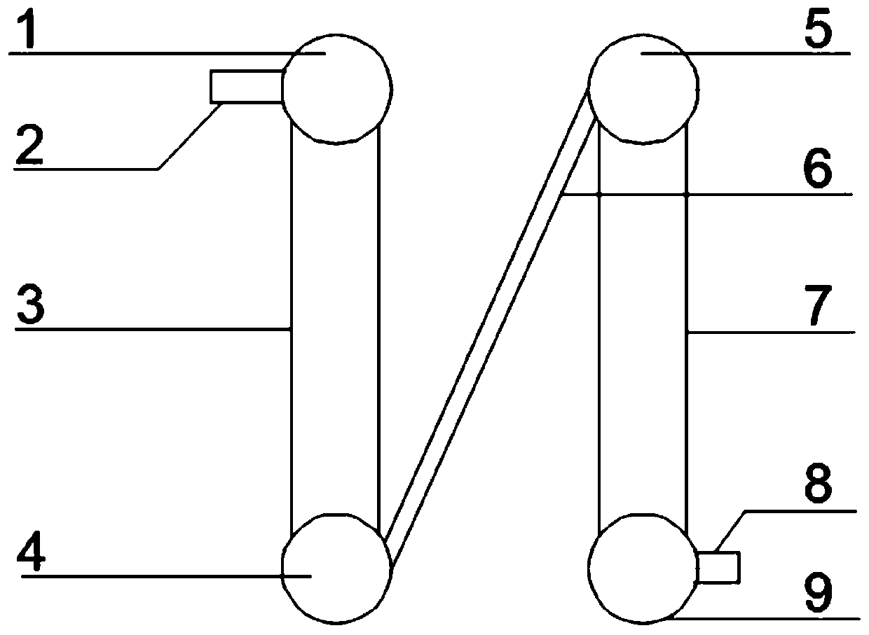
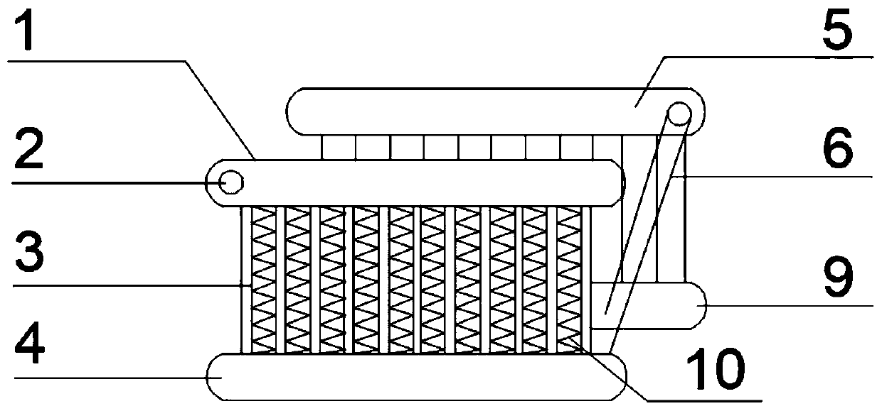
[0028] like figure 1 and figure 2 As shown, the embodiment of the present invention provides a microchannel heat exchanger, which includes two heat exchange units respectively the first heat exchange unit and the second heat exchange unit, specifically including the first header 1 horizontally arranged at the upper end, The second header 5, the third header 4 and the fourth header 9 horizontally arranged at the lower end, the first header 1, the second header 5, the third header 4 and the fourth header The flow tubes 9 are parallel to each other. The first header 1 communicates with the third header 4 through the first microchannel flat tube group 3 , and the second header 5 communicates with the fourth header 9 through the second microchannel flat tube group 7 .
[0029] Wherein, one side of the first header 1 is provided with a first interface 2, and one side of the fourth header 9 is provided with a second interface 8, in order to circulate the circulating medium in the ...
Embodiment 2
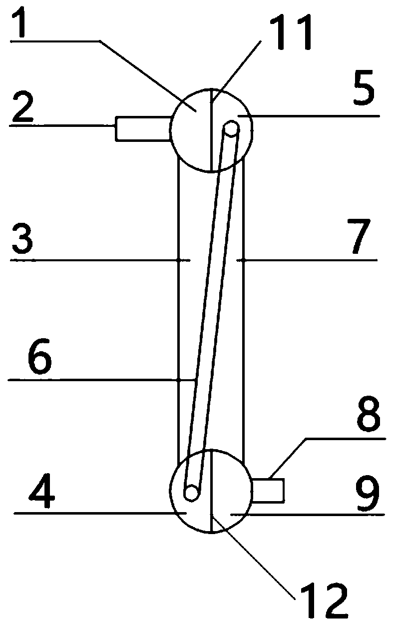
[0033] like image 3 and Figure 4 As shown, the second embodiment is basically the same as the first embodiment. For the sake of brevity, in the description process of this embodiment, the same technical features as the first embodiment will not be described, and only the second embodiment and the first embodiment will be described. the difference:
[0034] The first header 1 and the second header 5 are separated by the first partition 11 arranged along the length direction in the upper header, so that the first header 1 and the second header 5 form an independent circulation The medium circulation channel does not interfere with each other.
[0035] The third header 4 and the fourth header 9 are separated by the second partition 12 arranged along the length direction in the lower header, so that the third header 4 and the fourth header 9 form an independent circulation The medium circulation channel does not interfere with each other.
Embodiment 3
[0037] like Figure 5 and Figure 6 As shown, the third embodiment is basically the same as the first embodiment. For the sake of brevity, in the description process of this embodiment, the same technical features as the first embodiment will not be described, and only the third embodiment and the first embodiment will be described. the difference:
[0038]The first header 1 and the second header 5 are separated by a third partition 13 arranged inside the upper header and along its cross-sectional direction, so that the first header 1 and the second header 5 Form an independent circulating medium circulation channel without interfering with each other.
[0039] The third header 4 and the fourth header 9 are separated by the inside of the lower header and the fourth partition 14 arranged along its cross-sectional direction, so that the third header 4 and the fourth header 9 Form an independent circulating medium circulation channel without interfering with each other.
[00...
PUM
 Abstract
Description
Claims
Application Information
 - R&D
- Intellectual Property
- Life Sciences
- Materials
- Tech Scout
- Unparalleled Data Quality
- Higher Quality Content
- 60% Fewer Hallucinations
Browse by: Latest US Patents, China's latest patents, Technical Efficacy Thesaurus, Application Domain, Technology Topic, Popular Technical Reports.
© 2025 PatSnap. All rights reserved.Legal|Privacy policy|Modern Slavery Act Transparency Statement|Sitemap|About US| Contact US: help@patsnap.com