Contour line surveying and mapping auxiliary device
An auxiliary device and contour line technology, applied in the field of map surveying and mapping, can solve the problems of shortening the service life of the camera device, insufficient imaging resolution, corrosion of internal components, etc., and achieve the effects of good recording effect, long service life, and clear shooting.
- Summary
- Abstract
- Description
- Claims
- Application Information
AI Technical Summary
Problems solved by technology
Method used
Image
Examples
Embodiment 1
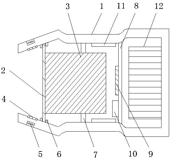
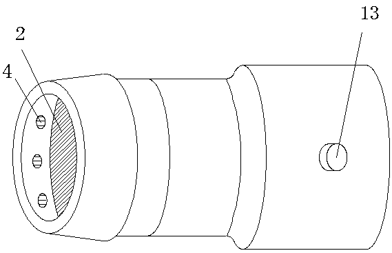
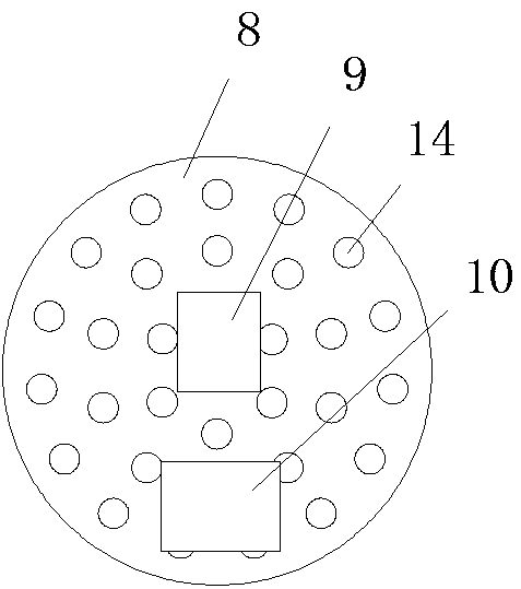
[0020] like Figure 1-5 As shown, a contour line surveying and mapping auxiliary device includes a camera device 1, a glass lens 2 is arranged in front of the camera device 1, and a shooting and imaging area 3 is arranged behind the glass lens 2, and the shooting and imaging area 3 It is fixed inside the imaging device 1 by the clamping plate 7, and the front part of the glass lens 2 is also provided with a heating wire 4, and the oblique lower part of the heating wire 4 is provided with a mini fan 5, and the glass lens 2 is fixed on the camera by a fixing ring 6. In the camera device 1, a ventilating plate 8 is arranged behind the shooting and imaging area 3, a control unit 9 and a power supply 10 are arranged on the ventilating plate 8, and evenly distributed through holes 14 are arranged on the ventilating plate 8. A humidity sensor 11 is arranged between the air-permeable plate 8 and the clamping plate 7 , a heating pipe 12 is arranged at the rear of the air-permeable plat...
Embodiment 2
[0023] like Figure 1-5 As shown, a contour line surveying and mapping auxiliary device includes a camera device 1, a glass lens 2 is arranged in front of the camera device 1, and a shooting and imaging area 3 is arranged behind the glass lens 2, and the shooting and imaging area 3 It is fixed inside the imaging device 1 by the clamping plate 7, and the front part of the glass lens 2 is also provided with a heating wire 4, and the oblique lower part of the heating wire 4 is provided with a mini fan 5, and the glass lens 2 is fixed on the camera by a fixing ring 6. In the camera device 1, a ventilating plate 8 is arranged behind the shooting and imaging area 3, a control unit 9 and a power supply 10 are arranged on the ventilating plate 8, and evenly distributed through holes 14 are arranged on the ventilating plate 8. A humidity sensor 11 is arranged between the air-permeable plate 8 and the clamping plate 7 , a heating pipe 12 is arranged at the rear of the air-permeable plat...
PUM
 Abstract
Description
Claims
Application Information
 - R&D
- Intellectual Property
- Life Sciences
- Materials
- Tech Scout
- Unparalleled Data Quality
- Higher Quality Content
- 60% Fewer Hallucinations
Browse by: Latest US Patents, China's latest patents, Technical Efficacy Thesaurus, Application Domain, Technology Topic, Popular Technical Reports.
© 2025 PatSnap. All rights reserved.Legal|Privacy policy|Modern Slavery Act Transparency Statement|Sitemap|About US| Contact US: help@patsnap.com


