An automatic transfer switch appliance with re-buckle function

A technology of automatic transfer switches and electrical appliances, which is applied in the direction of electric switches, circuits, electrical components, etc., can solve the problems of increased power consumption of equipment, unfavorable energy saving, large resistance torque of mechanisms, etc., and achieves extended service life of mechanisms, small space occupation, and mechanism The effect of small force

Active Publication Date: 2020-03-31
LEGRAND LOW VOLTAGE ELECTRICAL APPLIANCES WUXI
View PDF4 Cites 0 Cited by
  • Summary
  • Abstract
  • Description
  • Claims
  • Application Information

AI Technical Summary

Problems solved by technology

This mechanism controls the rotation of the rocker arm through the control wheel. One side of the rocker arm controls the commonly used side guide plate slider so that when the commonly used molded case circuit breaker is ready to close, the other side of the rocker arm is in the state of ready to open. The operating mechanism needs to be at the same time Two actions are performed, so the mechanism resistance torque of the operating mechanism is very large, and the molded case circuit breaker may trip when the line is overloaded during use. The current mechanism does not have re-clamping operation or during the re-clamping operation, The control wheel is subjected to closing force on one side and re-deduction force on the other side at the same time, and the handle of the circuit breaker is in a compressed state for a long time, which affects the service life of the circuit breaker, and requires a larger power motor, which increases the power consumption of the equipment, which is not conducive to energy saving

Method used


Image

  • An automatic transfer switch appliance with re-buckle function
  • An automatic transfer switch appliance with re-buckle function
  • An automatic transfer switch appliance with re-buckle function

Examples


Embodiment Construction

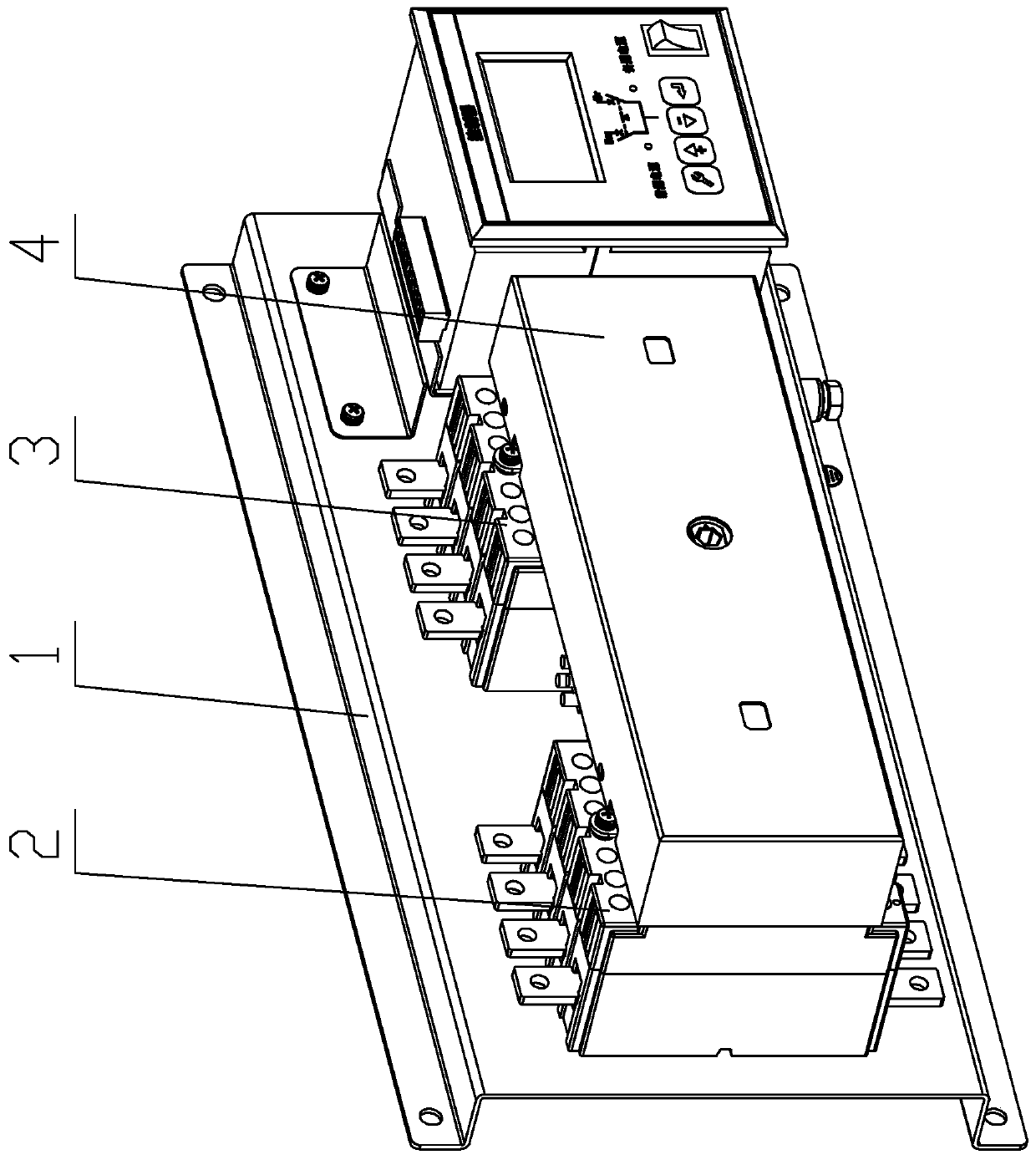
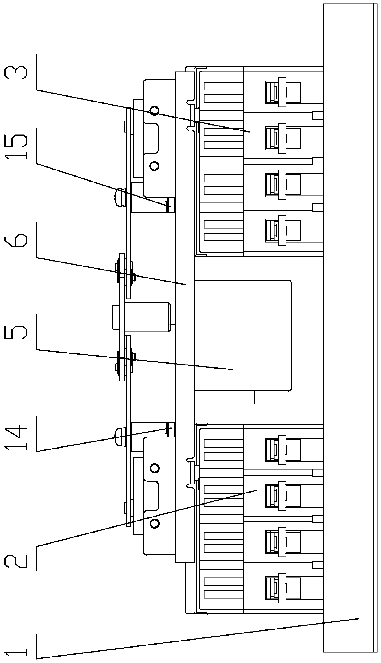
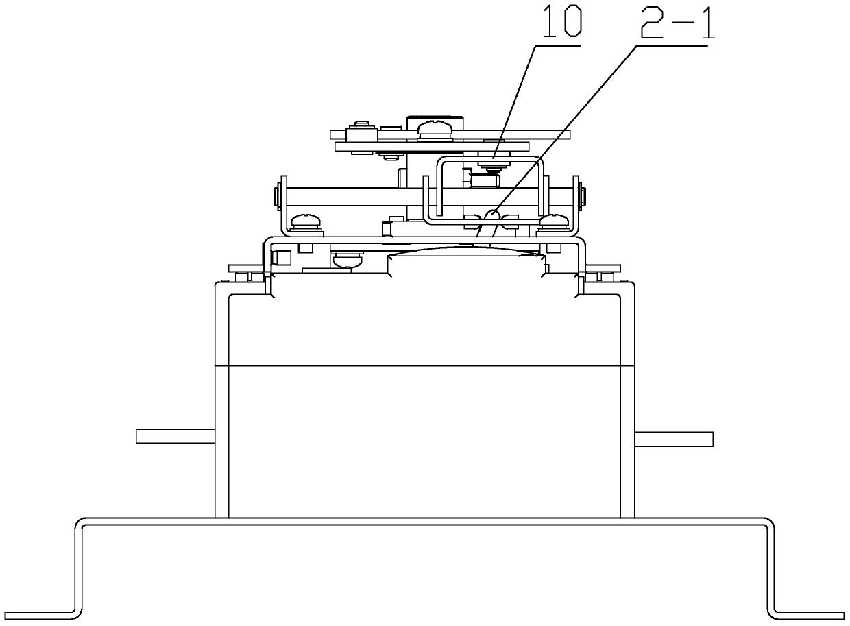
[0027] The specific embodiments of the present invention will be further described below in conjunction with the accompanying drawings.

[0028] Figure 1-10 Including 1. Mounting plate, 2. Common power module, 2-1. Common power switch handle, 3. Spare power module, 3-1. Spare power switch handle, 4. Shell, 5. Motor, 6. Fixed plate , 7. Control wheel, 7-1. The first shaft of the control wheel, 7-2. The second shaft of the control wheel, 7-3. The common closing operation surface of the control wheel, 7-4. The spare closing operation surface of the control wheel, 7-5. Commonly used re-buckle operation boss of the control wheel, 7-6. Spare re-buckle operation boss of the control wheel, 7-7. The first limit slot of the control wheel, 7-8. The second limit slot of the control wheel, 8. Commonly used rocker arm, 8-1. Commonly used rocker arm first axis, 8-2. Commonly used rocker arm second axis, 8-3. Commonly used rocker arm long slot, 9. Spare rocker arm, 9-1. Spare rocker arm Th...


PUM


Abstract

The invention relates to an automatic transfer switching device with a re-trip function. The automatic transfer switching device comprises a mounting plate, wherein a frequently-used power module anda backup power module are mounted at two ends of the mounting plate. A switch-off and switch-on operation mechanism is set between the frequently-used power module and a backup power module. The switch-off and switch-on operation mechanism realizes switching and interlocking between switch-off and switch-on of the automatic transfer switching device with the re-trip function. The switch-off and switch-on operation mechanism comprises a motor and a fixing plate. The fixing plate is mounted on the frequently-used power module and the backup power module. The motor is mounted under the fixing plate. A control wheel is mounted at an output rotation shaft of the motor. At one side of the control wheel, a frequently-used rocker arm drives a frequently-used power guide plate to carry out linear motion along a frequently-used power guide rod shaft. At the other side of the control wheel, a backup rocker arm drives a backup power guide plate to carry out the linear motion along a backup power guide rod shaft. Through utilization of the invention, the automatic transfer switching device with the re-trip function can carry out the interlocking reliably; in an operation process, the automatictransfer switching device with the re-trip function is relatively low in mechanism stress, so the motor with a relative low power can be employed and energy saving and emission reduction are facilitated; and the mechanism stress is relatively low, so service life of the mechanism can be extended.

Description

technical field [0001] The invention belongs to the technical field of low-voltage electrical equipment, and in particular relates to an automatic switch electrical appliance with a rebuckle function. Background technique [0002] In today's era, the demand for electricity and the stability of power supply are increasing, and the importance of automatic transfer switching appliances is increasing. As a conversion between two power sources, it provides a continuous and reliable power source for the load to ensure continuous operation of important loads. [0003] The current automatic transfer switch equipment includes two molded case circuit breakers, a motor and a control wheel fixed on the motor shaft. Two rocker arms are symmetrically installed on both sides of the control wheel. The rotating shaft on the control wheel cooperates to form the rotation of the rocker arm. The other end of the rocker arm is provided with a rotating shaft, which is located in the groove of the...

Claims


Application Information

Patent Timeline
Patent Type & Authority Patents(China)
IPC IPC(8): H01H9/26H01H9/00
Inventor 陈浩菁陈鑫龙张洪献高杰韩瑄林萍
Owner LEGRAND LOW VOLTAGE ELECTRICAL APPLIANCES WUXI
Why Eureka
Try Eureka