Novel three-station knife switch switching operation device mechanism

A switching device and knife switch operation technology, applied to high-voltage air circuit breakers, air switch components, electrical components, etc., can solve the problems of difficult operation, large space occupation, and complex structure, and achieve small space occupation, beautiful appearance, Simple operation effect

Pending Publication Date: 2020-05-19
福建逢兴机电设备有限公司
View PDF0 Cites 0 Cited by
  • Summary
  • Abstract
  • Description
  • Claims
  • Application Information

AI Technical Summary

Problems solved by technology

[0002] The current vacuum circuit breaker has a part of the knife switch structure that is a three-station structure. The so-called three-station structure is that the isolation knife and the grounding knife are the same knife installed on the upper end of the pole for closing and opening. 1. Grounding sequence rotation action. This structure operation has a characteristic that it must be operated in two steps from closing to opening and from opening to grounding. It is necessary to ensure a reliable knife switch switching operation when opening. It is realized by the device mechanism. At present, the operating knife switch switching device mechanism in the market is a gear structure. This structure uses the operating handle to drive the gear to link the main shaft to realize closing, opening and grounding. Although it is reliable, the structure is complicated. It takes up a lot of space, and the two-step operation position is operated separately in two places, which is not easy to operate

Method used


Image

  • Novel three-station knife switch switching operation device mechanism
  • Novel three-station knife switch switching operation device mechanism
  • Novel three-station knife switch switching operation device mechanism

Examples


Embodiment Construction

[0017] Below in conjunction with accompanying drawing and embodiment the present invention will be further described:

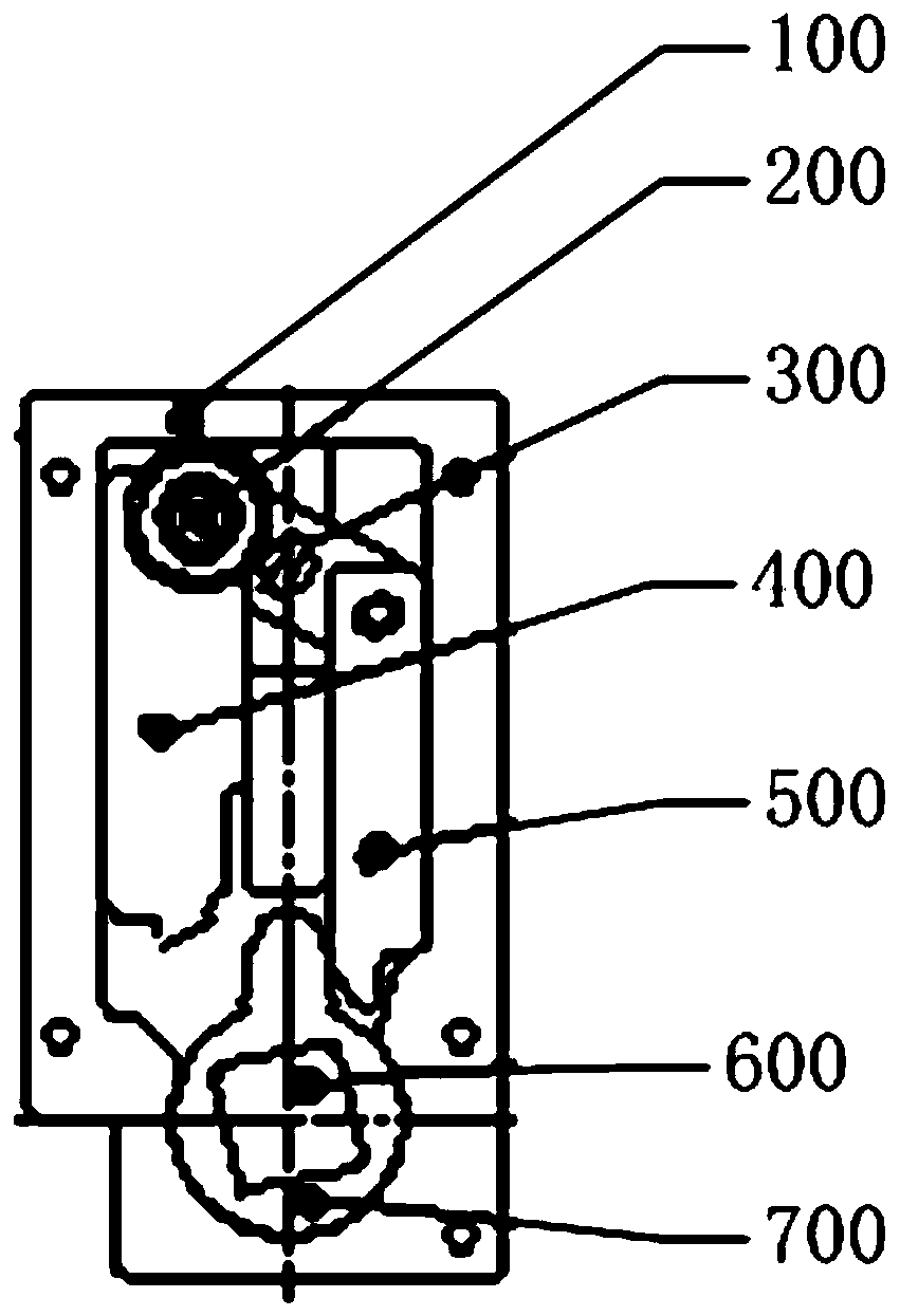
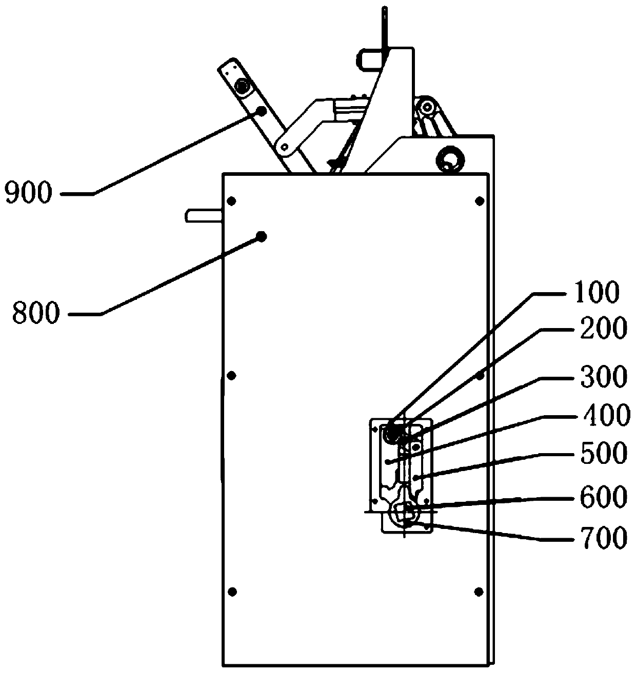
[0018] Such as Figure 1-2 As shown, in a specific embodiment of the present invention, a novel three-position knife switch switching operation device mechanism is provided, and the mechanism includes a mechanism base 100, a knife switch handle 200, a linkage plate 300, and a first limit block 400 , the second limiting block 500, the main shaft 600, the knife switch operation sleeve 700; the first limiting block 400 is a grounding and opening limiting block; the second limiting block 500 is a closing and opening limiting block; The first limiting block 400 is installed on the first side of the mechanism base 100; the second limiting block 500 is installed on the second side of the mechanism base 100; the first side and the second side are two sides that are not adjacent; the first limiting block 400, the second limiting block 500 and the mechanism base 100 a...


PUM


Abstract

The invention discloses a novel three-station knife switch switching operation device mechanism, which comprises a mechanism base, a knife switch switching handle, a linkage plate, a first limiting block, a second limiting block, a main shaft and a knife switch operation sleeve. The first limiting block is a grounding and opening limiting block; the second limiting block is a closing and opening limiting block; the first limiting block is arranged on the first side edge of the mechanism base; the second limiting block is arranged on the second side edge of the mechanism base; the first side edge and the second side edge are two non-adjacent side edges; the first limiting block and the second limiting block are connected with the mechanism base in a sliding manner; the two ends of the linkage plate are connected with the first limiting block and the second limiting block correspondingly; the knife switch switching handle is arranged on the linkage plate; the knife switch operating sleeve sleeves the main shaft; the rotation center of the main shaft coincides with the rotation center of the knife switch operating sleeve. The mechanism is simple and reliable in structure, small in occupied space, easy to operate and maintain, simple in knife switch switching and reliable in interlocking.

Description

technical field [0001] The invention relates to the technical field of a three-station knife switch, in particular to a novel switching operation device mechanism for a three-station knife switch. Background technique [0002] The current vacuum circuit breaker has a part of the knife switch structure that is a three-station structure. The so-called three-station structure is that the isolation knife and the grounding knife are the same knife installed on the upper end of the pole for closing and opening. 1. Grounding sequence rotation action. This structure operation has a characteristic that it must be operated in two steps from closing to opening and from opening to grounding. It is necessary to ensure a reliable knife switch switching operation when opening. It is realized by the device mechanism. At present, the operating knife switch switching device mechanism in the market is a gear structure. This structure uses the operating handle to drive the gear to link the main...

Claims


Application Information

Patent Timeline
Patent Type & Authority Applications(China)
IPC IPC(8): H01H31/02H01H9/26
CPCH01H9/26H01H31/02H01H31/026
Inventor 苏太育林增恒倪敏敏张春玉陈秋河熊美英陈柏湖江若凡董燕天熊锦昌倪欢欢张华榕邓逢锌郑锦芳吴建兵张锦澎李云禄乐丽珍吴卫明曾伟德
Owner 福建逢兴机电设备有限公司
Why Eureka
Try Eureka