Clutch discs, friction clutch units and drive trains

A technology for friction clutches and clutch discs, which is applied to the fields of dry clutches, friction clutch devices themselves, motor vehicle transmissions, and friction clutch devices, and can solve problems such as increased component loads and increased wear of clutch discs 30

Active Publication Date: 2022-02-18
SCHAEFFLER TECH AG & CO KG
View PDF21 Cites 0 Cited by
  • Summary
  • Abstract
  • Description
  • Claims
  • Application Information

AI Technical Summary

Problems solved by technology

The resulting tension in the clutch disk 30 leads to increased component loading and increased wear of the clutch disk 30 , especially in the region of the spring guide 51

Method used


Image

  • Clutch discs, friction clutch units and drive trains
  • Clutch discs, friction clutch units and drive trains
  • Clutch discs, friction clutch units and drive trains

Examples


Embodiment Construction

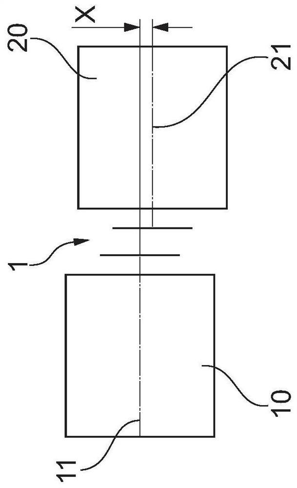
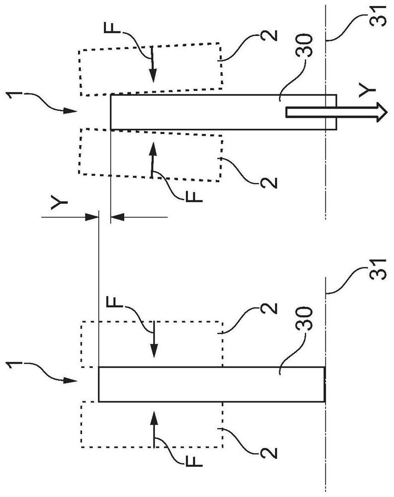
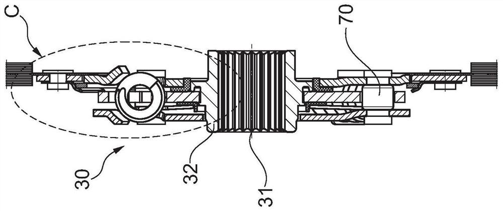
[0056] discussed Figure 1 to Figure 4 , used to illustrate the prior art.

[0057] Figure 5 and 6 A clutch disc 30 according to the present invention is shown in , wherein, Image 6 shown in enlarged view Figure 5 Partial area D shown in .

[0058] The structure of the clutch disc 30 according to the present invention is substantially similar to image 3 and Figure 4 The described structure of the conventional clutch disc.

[0059] The clutch disc according to the invention differs from conventional clutch discs essentially in that, in addition to the first hub flange 40 , the clutch disc according to the invention has a second hub flange 41 , which is opposite to the first hub flange 40 . They are arranged in parallel and rotationally symmetrical to the first hub flange 40 .

[0060] Depending on the load direction (pulling or pushing), at least one of the hub flanges 40 , 41 is engaged on the hub 32 so that torque can be transmitted from the hub flanges 40 , 41 t...


PUM


Abstract

A clutch disc for a friction clutch device as well as the friction clutch device itself and a drive train. The clutch disc (30) comprises a hub (32) for torque-proof connection to a shaft, a friction element (33) for frictionally inputting torque into the clutch disc (30) and a first hub flange (40 ) and the second hub flange (41), wherein at least the first hub flange (40) is connected to the hub (32) in a torque-proof manner, wherein the clutch disc (30) has a spring element (50) which is The two hub flanges are mechanically coupled to each other between the two hub flanges so that the hub flanges can rotate relative to each other, wherein the clutch disc (30) is configured such that the two hub flanges (40, 41) Can be laterally offset from each other. With the clutch disk proposed here, lateral or radial offsets or radial displacements can be compensated, while at the same time ensuring a long service life due to the reduced friction ratio at the damping spring of the clutch disk.

Description

technical field [0001] The present invention relates to a clutch disc for a friction clutch device, in particular for a dry clutch, and to the friction clutch device itself. Furthermore, the invention relates to a drive train, in particular a drive train of a motor vehicle, which has a friction clutch arrangement according to the invention. Background technique [0002] A clutch disk is known as a component part of a clutch or clutch arrangement for transmitting torque between a drive machine and a transmission. Such a clutch disk is usually coupled centrally to a shaft (eg a transmission shaft) and can be applied by a correspondingly configured clutch element when the friction linings of the clutch disk arranged on the radially outer side are subjected to an axial force torque. [0003] It is important for functionality and to ensure a long service life that the clutch disk is subjected, as far as possible, to only theoretically provided loads during use and therefore und...

Claims


Application Information

Patent Timeline
Patent Type & Authority Patents(China)
IPC IPC(8): F16D13/64F16F15/12
CPCF16D13/644F16F15/123
Inventor A·福伊特S·莱曼
Owner SCHAEFFLER TECH AG & CO KG
Why Eureka
Try Eureka