
Knob switch structure and automobile

A knob switch, knob technology, applied in electrical switches, electrical components, circuits, etc., can solve the problems of inability to fold the exterior rearview mirror, knob stay, unstable feeling, etc., and achieve smooth and smooth mirror adjustment and folding, and stable and continuous rotation. , the effect of smooth feel

Active Publication Date: 2019-05-24
GEELY AUTOMOBILE INST NINGBO CO LTD +1
View PDF6 Cites 0 Cited by
  • Summary
  • Abstract
  • Description
  • Claims
  • Application Information

AI Technical Summary

Problems solved by technology

However, because this design only has a single-sided gear slot structure, during the rotation of the knob, the internal rotating block will be forced on one side when it rotates together, and the knob will shake slightly and feel unstable.
[0007] In addition, in the above two design schemes, when rotating to the folding gear, there is no corresponding force value feel. If the operator exerts a small force, it is easy for the knob assembly to stay on the middle line of the knob, which cannot make the rear view of the car mirror folding

Method used


Image

  • Knob switch structure and automobile
  • Knob switch structure and automobile
  • Knob switch structure and automobile

Examples


Embodiment 1

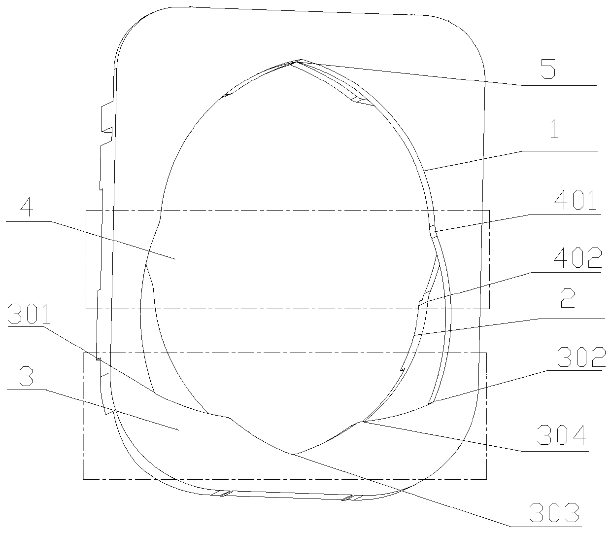
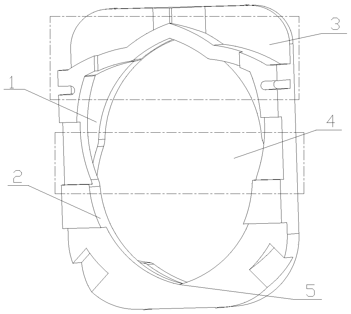
[0040] like Figure 1 to Figure 5As shown, a rotary switch structure includes a housing 7, a swing rod 10, a rotor 11 and a gear plate 13, the gear plate 13 is fixedly arranged on the housing 7, and the rotor 11 is sleeved on the swing rod 10, rotates synchronously with the swing rod 10, the shift plate 13 includes a first layer and a second layer, the first layer is formed with a through first opening 1, and the second layer is formed with There is a through second opening 2, the first opening 1 includes a smooth shift part 3 and a sudden shift area 4, the second opening 2 has the same structure as the first opening 1, the first The second opening 2 rotates 180° along the axial centerline of the first opening 1 to coincide with the first opening 1;

[0041] It also includes a first prop 15 and a second prop 16, one end of the first prop 15 is fixedly connected to the rotor 11, the other end slides along the inner wall of the first opening 1, and the second prop 16, one end ...

Embodiment 2

[0052] Embodiment 2: be the preferred embodiment of embodiment 1,

[0053] like Figure 1 to Figure 5 Shown: a rotary switch structure, including a housing 7, a swing rod 10, a rotor 11 and a gear plate 13, the gear plate 13 is fixedly arranged on the housing 7, and the rotor 11 is sleeved on the swing rod 10, rotates synchronously with the swing rod 10, the shift plate 13 includes a first layer and a second layer, the first layer is formed with a through first opening 1, and the second layer is formed with There is a through second opening 2, the first opening 1 includes a smooth shift part 3 and a sudden shift area 4, the second opening 2 has the same structure as the first opening 1, the first The second opening 2 rotates 180° along the axial centerline of the first opening 1 to coincide with the first opening 1;

[0054] It also includes a first prop 15 and a second prop 16, one end of the first prop 15 is fixedly connected to the rotor 11, the other end slides along the...

Embodiment 3

[0076] Embodiment 3: be the preferred embodiment of embodiment 2

[0077] The difference with embodiment 2 is characterized in that:

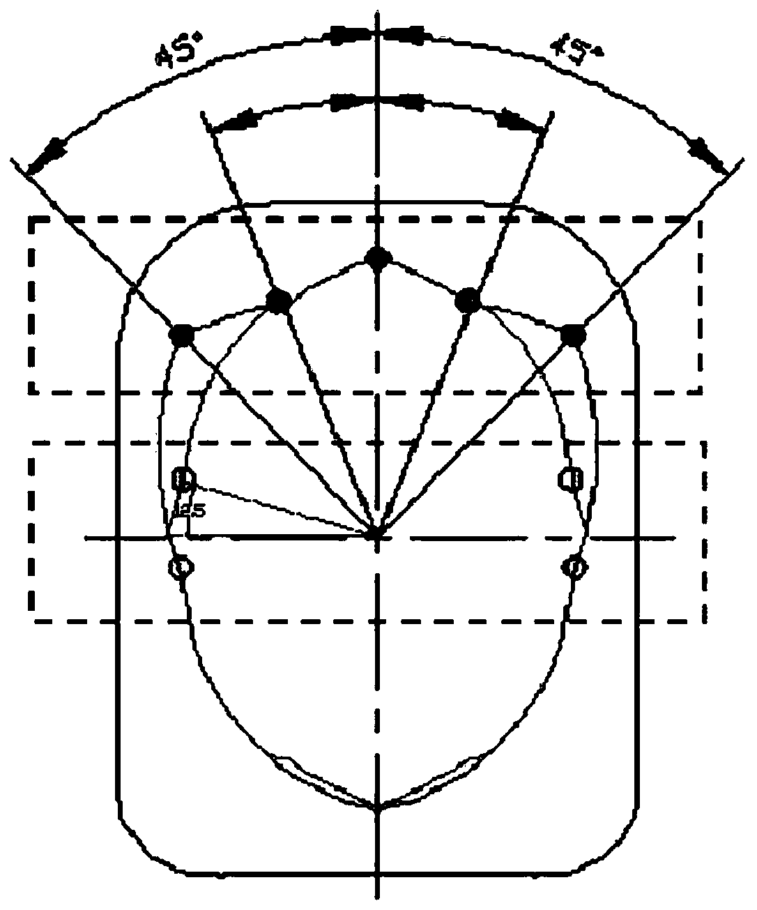
[0078] The angle between the centerline in the horizontal direction of the gear mutation area 4 of the first opening 1 and the first mutation point 401 is 10° or 15°, and the gear position of the second opening 2 The included angle between the horizontal center line of the mutation region 4 and the second mutation point 402 is 10° or 15°.

[0079] Described contact bridge 18 is provided with two, and two described contact bridges 18 are all provided with contact bridge pressure spring 19, and described movable contact 14 is provided with two, and two described movable contacts 14 are all provided with The movable contact compression spring 20 and the rotor 11 can be adjusted in different directions through the conduction of different contact bridges 18 .

[0080] Furthermore, the support pin 23 is fixedly connected to the swing rod 10 through...


PUM


Abstract

The invention discloses a knob switch structure, which comprises a housing, a swing rod, a rotor and a gear plate. The gear plate comprises a first layer and a second layer. A first through hole is formed in the first layer, and a second through hole is formed in the second layer. The first through hole comprises a smooth gear part and a gear sudden change area. The second through hole and the first through hole are of the same structure. The second through hole rotates by 180 degrees along the axial center line of the first through hole and coincides with the first through hole. The structurefurther comprises a first top column and a second top column. One end of the first top column is fixedly connected with the rotor, and the other end of the first top column slides along the inner wall of the first through hole. One end of the second top column is fixedly connected with the rotor, and the other end of the second top column slides along the inner wall of the second through hole. The first top column and the second top column are symmetrically arranged along the central axis of the rotor. The invention further discloses an automobile. The automobile comprises the knob switch structure. According to the invention, force values can be mutually offset, and the stable and smooth operation at each gear can be realized. The stagnation phenomenon can occur on the surface of the arranged gear abrupt change area at the horizontal position. Therefore, the smooth hand feeling is achieved.

Description

technical field [0001] The invention relates to the technical field of rotary switches, in particular to a rotary switch structure and an automobile. Background technique [0002] At present, there are two kinds of gear feel designs for the left (L) and right (R) mirror selection of the knob-type exterior rearview mirror switch: [0003] 1. When the knob is from "O" gear --> "L" or "R" gear, the force feel changes suddenly when the knob rotates to an angle of about 30°, and then reaches "L" or "R" through a 15° rotation angle When the knob returns from the "L" or "R" position to the "O" position, it is just the opposite. It first turns 15°, then the force value changes abruptly, and then returns to the "O" position through a 30° rotation angle. The sudden change of force feel is at the position of the 2 / 3 angle dividing line of "O" gear --> "L" or "R" gear. [0004] This design is due to the position of the sudden change point of the hand feeling force value at the p...

Claims


Application Information

Patent Timeline
Patent Type & Authority Applications(China)
IPC IPC(8): H01H19/02H01H19/10
Inventor 朱晋林
Owner GEELY AUTOMOBILE INST NINGBO CO LTD
Learn More