

Buffer hammer
A hammer and hammer head technology is applied in the field of buffer type hammers, which can solve the problems of hammer head damage and shortening service life, and achieve the effect of prolonging service life and good buffering.
- Summary
- Abstract
- Description
- Claims
- Application Information
AI Technical Summary
Problems solved by technology
Method used
Image

Examples
Embodiment Construction
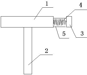
[0012] Such as figure 1 As shown, a buffer hammer includes a fixedly connected hammer head 1 and a handle 2. One end of the hammer head 1 is provided with a hammer block 3. The hammer block 3 is fixedly connected to the hammer head 1 through an elastic device. The elastic device is a strong spring 4. A guiding hose 5 is sheathed on the periphery of the elastic device.
[0013] The buffer type hammer protects the end of the hammer head through the hammer block connected by a strong spring, which plays a good buffer during the hammering process and prolongs the service life. The guide hose guides the spring to prevent The skew of the middle spring affects the use.
[0014] The above description is only illustrative, rather than restrictive, to the present invention. Those skilled in the art understand that many modifications, changes or the like can be made without departing from the spirit and scope defined by the appended claims. effect, but all will fall within the protecti...
PUM
 Abstract
Description
Claims
Application Information