Control method of electric temperature control mattress

A control method and mattress technology, applied to beds, other seating furniture, home appliances, etc., can solve the problems of power consumption and energy waste, and achieve the effect of reducing energy consumption and waste

Inactive Publication Date: 2019-06-04
QINGDAO HAIER AIR CONDITIONER GENERAL CORP LTD
6 Cites 0 Cited by

AI-Extracted Technical Summary

Problems solved by technology

For example, when the indoor unit of the air conditioner is cooling, the outdoor unit will dissipate the heat at the same time. Similarly, the refrigerator also needs to consume electric energy or dissipate the heat when cooling. On the other hand, the water heater need...

Abstract

The invention discloses a control method of an electric temperature control mattress, and belongs to the technical field of energy conservation. For the control method of the electric temperature control mattress, one or more heating parts are arranged on the electric temperature control mattress, the one or more heating parts are powered by a temperature difference power generation device, one end of the temperature difference power generation device is connected to a hot source device, and the other end of the temperature difference power generation device is connected to a cold source device. The method comprises the following steps: acquiring the target temperature and practical temperature of each heating part; and according to the difference value between the target temperature and practical temperature of each heating part, controlling the heating time of each heating part. For the control method of the electric temperature control mattress, the collecting and dispatching for waste energy are realized, then the use by other devices is available, therefore, the energy consumption and waste are reduced, and the purpose of energy conservation and emission reduction is realized.

Application Domain

Beds

Technology Topic

Heating timeEngineering +5

Image

  • Control method of electric temperature control mattress
  • Control method of electric temperature control mattress
  • Control method of electric temperature control mattress

Examples

  • Experimental program(1)

Example Embodiment

[0024] The following description and drawings fully illustrate specific embodiments of the present invention to enable those skilled in the art to practice them. Other implementations may include structural, logical, electrical, process, and other changes. The examples only represent possible changes. Unless explicitly required, individual components and functions are optional, and the order of operations can be changed. Parts and features of some embodiments may be included in or substituted for parts and features of other embodiments. The scope of the embodiments of the present invention includes the entire scope of the claims, and all available equivalents of the claims. In this document, each embodiment may be individually or collectively denoted by the term "invention", this is only for convenience, and if more than one invention is actually disclosed, it is not intended to automatically limit the scope of the application to any A single invention or inventive concept. In this article, relational terms such as first and second are only used to distinguish one entity or operation from another entity or operation, and do not require or imply any actual relationship or relationship between these entities or operations. order. Moreover, the terms "including", "including" or any other variants thereof are intended to cover non-exclusive inclusion, so that a process, method or device including a series of elements includes not only those elements, but also other elements not explicitly listed. Elements, or also include elements inherent to the process, method, or equipment. If there are no more restrictions, the element defined by the sentence "includes a..." does not exclude the existence of other same elements in the process, method, or device that includes the element. The various embodiments herein are described in a progressive manner, and each embodiment focuses on the differences from other embodiments, and the same or similar parts between the various embodiments can be referred to each other. For the methods, products, etc. disclosed in the embodiments, since they correspond to the methods disclosed in the embodiments, the description is relatively simple, and the relevant parts can be referred to the description of the method part.
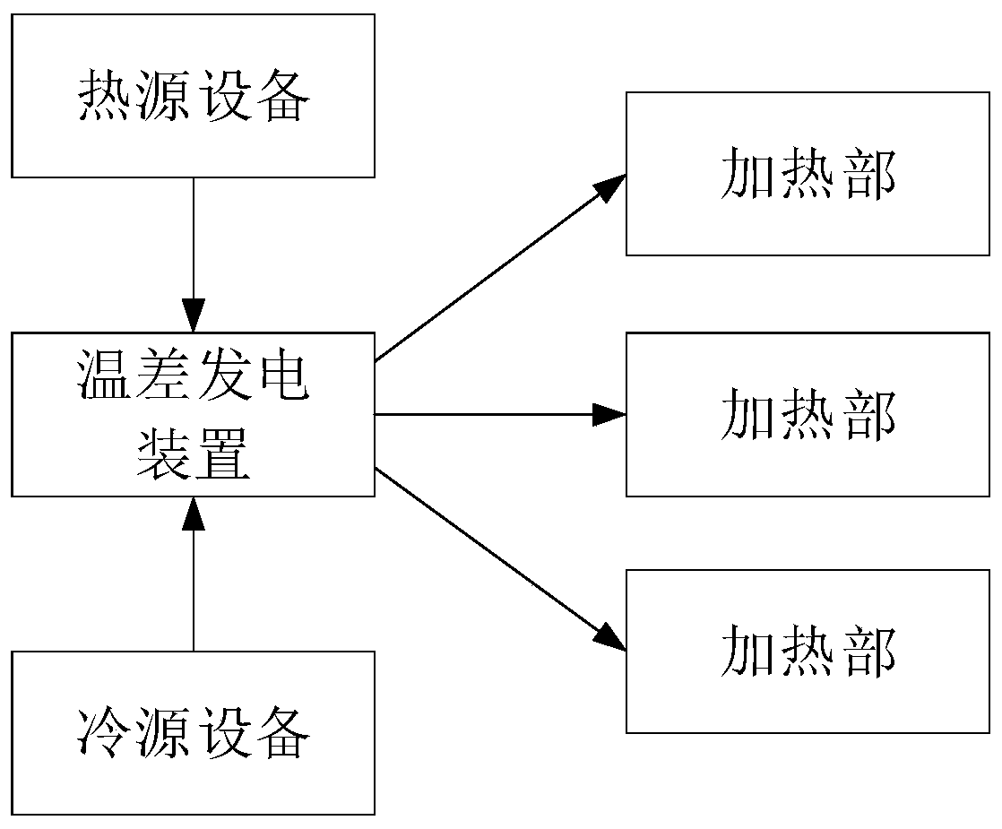
[0025] figure 1 An alternative embodiment of an electric temperature control mattress is shown.
[0026] In this alternative embodiment, one or more heating parts are provided on the electric temperature control mattress, and the heating part is powered by a thermoelectric power generation device. One end of the thermoelectric power generation device is connected to the heat source equipment, and the other end of the thermoelectric power generation device is connected to the cold Source device.
[0027] When the number of heating parts is one, the size of the heating part is slightly smaller than the size of the mattress. When the number of heating parts is multiple, the heating parts are arranged at positions corresponding to the human head, dry, legs, feet, etc.
[0028] Optionally, the heat source device is a household appliance that generates heat such as a refrigerator condenser, a condenser of an air conditioner in a cooling mode, and the like.
[0029] Optionally, the cold source device is a household appliance that generates cold energy such as an evaporator of an air conditioner in a heating mode.
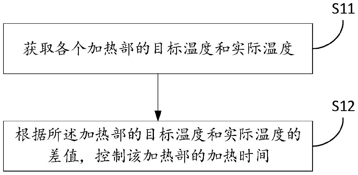
[0030] figure 2 An alternative embodiment of the control method of the electric temperature control mattress is shown.
[0031] In some optional embodiments, the control method is used to control the aforementioned electric temperature control mattress, and the control method includes the following steps: obtaining the target temperature and the actual temperature of each heating part; according to the target temperature and the actual temperature of the heating part The difference value controls the time that the heating unit communicates with the thermoelectric power generation device.
[0032] With this alternative embodiment, the time for the heating unit to communicate with the thermoelectric power generation device is controlled according to the difference between the target temperature and the actual temperature. If the temperature difference is large, the connection time is long, and if the temperature difference is small, the connection time is short. Each heating unit can be heated evenly or Cool down to ensure user experience.
[0033] Optionally, the target temperature is a preset temperature set by a user.
[0034] For example, when the temperature difference between the target temperature of a certain heating part and the actual temperature is large, more heat exchange is required, and the connection time between the heating part and the thermoelectric power generation device is controlled to be longer to ensure that the temperature rises faster.
[0035] Optionally, the target temperature is an average temperature of the heating part that is in operation, and the average value is obtained by obtaining the actual temperature of each heating part, and used as the target temperature.
[0036] Optionally, the actual temperature is obtained by a temperature sensor provided on the heating part.
[0037] In another optional embodiment, the method further includes: obtaining the number of heating parts that are running; and controlling the heating part to communicate with the thermoelectric power generation device in time sharing according to the number of heating parts that are running.
[0038] With this optional embodiment, when the number of heating parts in operation reaches a certain number, the time-sharing method is adopted to control the heating part connected to the thermoelectric power generation device to ensure the power supply in the thermoelectric power generation device, so that each heating part can Raise or cool evenly.
[0039] Optionally, the step of controlling the time-sharing communication between the heating part and the thermoelectric power generation device according to the number of heating parts in operation includes: when the number of heating parts in operation is less than a preset value, controlling the heating When the number of heating parts in operation is greater than a preset value, the heating part and the thermoelectric power generation device are controlled to be connected in time sharing.
[0040] By adopting this optional embodiment, the capacity of the thermoelectric power generation device can be optimized, and more heating part work can be supplied by thermoelectric power generation devices with a smaller capacity or a smaller number.
[0041] Optionally, when the number of heating parts in operation is greater than the preset value, the single-in-single-out switching mode is used to control the heating part that is connected and the heating part that exits. All heating parts adopt the single-in-single-out switching mode and The thermoelectric power generation device is cyclically connected.
[0042] In another optional embodiment, the method further includes: controlling the number of heating parts that are simultaneously connected to the thermoelectric power generation device according to the number of heating parts that are running and the difference between the target temperature and the actual temperature of each heating part.
[0043] With this optional embodiment, the stable operation of the system can be guaranteed.
[0044] For example, a heating section with a large difference between the target temperature and the actual temperature requires more heat exchange with the thermoelectric power generation device than a heating section with a small difference between the target temperature and the actual temperature. Therefore, the difference between the target temperature and the actual temperature It is an important basis for controlling the number of heating units connected to thermoelectric power generation devices. For example, for a heating unit with a large difference between the target temperature and the actual temperature, a single heating unit needs to exchange more heat. Therefore, the number of heating units connected to the thermoelectric power generation device at the same time is controlled to prevent insufficient power supply of the system. For another example, for a heating part with a small difference between the target temperature and the actual temperature, a single heating part needs to perform less heat exchange. Therefore, the thermoelectric power generation device can be connected to a larger number of the heating parts at the same time.
[0045] In another optional embodiment, the method further includes: controlling the heat exchange time between each heating part and the thermoelectric power generation device according to the number of heating parts in operation and the difference between the target temperature and the actual temperature of each heating part .
[0046] Optionally, when the heating part is in the heating mode, when the target temperature is higher than the actual temperature, the time that the heating part communicates with the thermoelectric power generation device is controlled, and when the target temperature is lower than the actual temperature, the heating part is controlled to be disconnected from the thermoelectric power generation device. Open the connection; when the heating part is in the cooling mode, when the target temperature is lower than the actual temperature, control the time that the heating part communicates with the thermoelectric power generation device; when the target temperature is higher than the actual temperature, control the heating part to disconnect the thermoelectric power generation device.
[0047] With this alternative embodiment, in the step of controlling the time for the heating part to communicate with the thermoelectric power generation device according to the number of heating parts in operation and the difference between the target temperature of the heating part and the actual temperature, each heating part is connected to the thermoelectric power generation device. The time is not the same. For the heating part with a large temperature difference between the target temperature and the actual temperature, control the heating part to communicate with the thermoelectric power generation device for a long time. For the heating part with a small temperature difference between the target temperature and the actual temperature, control the heating part and the thermoelectric power generation device The connection time is short, and therefore, the combination of the heating parts connected to the thermoelectric power generation device at the same time changes.
[0048] Optionally, the time for the heating part to communicate with the thermoelectric power generation device Among them, K is the proportional coefficient, ΔT n Is the difference between the target temperature and actual temperature of the heating part, ΔT av Is the average value of the difference between the target temperature and the actual temperature of the heating part that is running, t base Open time as a benchmark.
[0049] Optionally, the reference opening time t base Set according to the number of heating sections that are running. Optionally, the less the number of heating parts is running, the reference opening time t base The longer, the greater the number of heating sections that are running, and the reference open time t base Shorter.
[0050] Optionally, when the heating part is in heating mode, ΔT n Is the difference between the target temperature minus the actual temperature, when the heating part is in the cooling mode, ΔT n Is the difference between the actual temperature minus the target temperature. When ΔT n When ≤0, the heating part stops communicating with the thermoelectric power generation device.
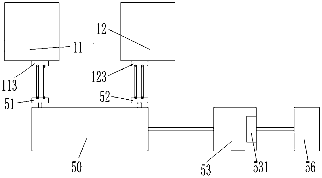
[0051] image 3 An alternative embodiment of the thermoelectric power generation device is shown.
[0052] In the embodiment of the present invention, the thermoelectric power generation device 50 is a technology that uses the Seebeck effect and Peltier effect of semiconductor materials to directly convert heat energy and electrical energy. Specifically, when the semiconductor material is unevenly heated at both ends, the carriers therein migrate, thereby forming a potential difference between the two ends. The thermoelectric power generation device 50 may be a known device.
[0053] One end (hot end) of the thermoelectric power generation device 50 is in communication with the heat source equipment, and the other end (cold end) is in communication with the cold source equipment, with various communication modes. For example, the first connection method, such as image 3 As shown, using a fluid medium as a carrier, a hot-end heat exchange device I113 is installed on the side of the heat source device 11, and a hot-end heat exchange device I51 is also installed on the hot end of the thermoelectric power generation device 50. The two heat exchange devices are connected through two pipelines. (113 and 51) are connected to form a hot-end circulation loop, and a fluid medium flows in the hot-end circulation loop to transport the heat in the heat source equipment 11 to the hot end of the thermoelectric power generation device 50. Similarly, between the cold source equipment 12 and the cold end of the thermoelectric power generation device 50, two heat exchange devices (cold end heat exchange device I 123 and cold end heat exchange device II 52) form a cold end circulation loop, and the fluid medium is in this Flow in the cold end circulation loop, and transport the cold in the cold source equipment to the cold end of the thermoelectric power generation device 50. A temperature difference is formed between the hot end and the cold end of the thermoelectric power generation device 50, thereby forming a potential difference. As another example, the second connection method can directly use the heat conductor to connect the hot end of the thermoelectric power generation device 50 to the heat source equipment, and the cold end to the cold source equipment, and use the heat conductor to transfer heat and cold to the thermoelectric power generation device. 50 ends.
[0054] Optionally, the number of heat source devices 11 is one or more, and the number of cold source devices 12 is also one or more.
[0055] In an alternative embodiment, such as image 3 As shown, the electrical energy output end of the thermoelectric power generation device 50 is electrically connected to the power storage device 53. The energy storage device 53 may be a conventional electricity storage device with a power storage function, such as a lithium ion battery, a lead-acid battery, and the like. An electric voltage adjustment module 531 is provided at the electric energy output end of the electric storage device 53 to provide electric energy with a matching voltage to the electric equipment 56.
[0056] Those skilled in the art may realize that the units and algorithm steps of the examples described in combination with the embodiments disclosed in this document can be implemented by electronic hardware or a combination of computer software and electronic hardware. Whether these functions are executed by hardware or software depends on the specific application and design constraints of the technical solution. Those skilled in the art can use different methods for each specific application to implement the described functions, but such implementation should not be considered as going beyond the scope of the present invention. Those skilled in the art can clearly understand that, for convenience and concise description, the specific working process of the above-described system, device, and unit can refer to the corresponding process in the foregoing method embodiment, and details are not described herein again.
[0057] In the embodiments disclosed herein, it should be understood that the disclosed methods and products (including but not limited to devices, equipment, etc.) can be implemented in other ways. For example, the device embodiments described above are merely illustrative. For example, the division of the units is only a logical function division, and there may be other divisions in actual implementation, for example, multiple units or components may be combined or It can be integrated into another system, or some features can be ignored or not implemented. In addition, the displayed or discussed mutual coupling or direct coupling or communication connection may be indirect coupling or communication connection through some interfaces, devices or units, and may be in electrical, mechanical or other forms. The units described as separate components may or may not be physically separated, and the components displayed as units may or may not be physical units, that is, they may be located in one place, or they may be distributed on multiple network units. Some or all of the units may be selected according to actual needs to achieve the objectives of the solutions of the embodiments. In addition, the functional units in each embodiment of the present invention may be integrated into one processing unit, or each unit may exist alone physically, or two or more units may be integrated into one unit.
[0058] It should be understood that the flowcharts and block diagrams in the accompanying drawings show the possible implementation architecture, functions, and operations of the system, method, and computer program product according to multiple embodiments of the present invention. In this regard, each block in the flowchart or block diagram may represent a module, program segment, or part of the code, and the module, program segment, or part of the code contains one or more functions for realizing the specified logic function. Executable instructions. It should also be noted that, in some alternative implementations, the functions marked in the block may also occur in a different order from the order marked in the drawings. For example, two consecutive blocks can actually be executed in parallel, or they can sometimes be executed in the reverse order, depending on the functions involved. It should also be noted that each block in the block diagram and/or flowchart, and the combination of the blocks in the block diagram and/or flowchart, can be implemented by a dedicated hardware-based system that performs the specified functions or actions Or it can be realized by a combination of dedicated hardware and computer instructions. The present invention is not limited to the processes and structures that have been described above and shown in the drawings, and various modifications and changes can be made without departing from its scope. The scope of the present invention is only limited by the appended claims.

PUM

no PUM

Description & Claims & Application Information

We can also present the details of the Description, Claims and Application information to help users get a comprehensive understanding of the technical details of the patent, such as background art, summary of invention, brief description of drawings, description of embodiments, and other original content. On the other hand, users can also determine the specific scope of protection of the technology through the list of claims; as well as understand the changes in the life cycle of the technology with the presentation of the patent timeline. Login to view more.

Similar technology patents

Control method of energy system

InactiveCN109764558AReduce energy consumption and waste
Owner:QINGDAO HAIER AIR CONDITIONER GENERAL CORP LTD

Energy system and heater temperature adjusting control method thereof

ActiveCN109764397AReduce energy consumption and waste
Owner:QINGDAO HAIER AIR CONDITIONER GENERAL CORP LTD +1

Control method of energy system

ActiveCN109764562AReduce energy consumption and waste
Owner:QINGDAO HAIER AIR CONDITIONER GENERAL CORP LTD +1

Control method of energy system

ActiveCN109764453AReduce energy consumption and waste
Owner:QINGDAO HAIER AIR CONDITIONER GENERAL CORP LTD +1

Energy system as well as control method of bed body temperature adjustment of energy system

ActiveCN109757917AReduce energy consumption and waste
Owner:QINGDAO HAIER AIR CONDITIONER GENERAL CORP LTD

Classification and recommendation of technical efficacy words

  • Reduce energy consumption and waste

Energy system and heater temperature adjusting control method thereof

ActiveCN109764397AReduce energy consumption and waste
Owner:QINGDAO HAIER AIR CONDITIONER GENERAL CORP LTD +1

Control method of energy system

InactiveCN109764558AReduce energy consumption and waste
Owner:QINGDAO HAIER AIR CONDITIONER GENERAL CORP LTD

Control method of energy system

ActiveCN109764453AReduce energy consumption and waste
Owner:QINGDAO HAIER AIR CONDITIONER GENERAL CORP LTD +1

Energy system as well as control method of bed body temperature adjustment of energy system

ActiveCN109757917AReduce energy consumption and waste
Owner:QINGDAO HAIER AIR CONDITIONER GENERAL CORP LTD

Control method of energy system

ActiveCN109764562AReduce energy consumption and waste
Owner:QINGDAO HAIER AIR CONDITIONER GENERAL CORP LTD +1
Why Eureka
Try Eureka