Control method of energy system
An energy system and control method technology, applied in solar heating systems, solar collector controllers, solar thermal energy and other directions, can solve the problems of inconvenient maintenance, inconvenience in daily life of the entire unit building, etc., and achieve the effect of reducing energy consumption and waste.
Active Publication Date: 2019-05-17
QINGDAO HAIER AIR CONDITIONER GENERAL CORP LTD +1
9 Cites 0 Cited by
AI-Extracted Technical Summary
Problems solved by technology
[0003] However, the current solar water heater needs to lead cold water to the outdoor vacuum heat collecting tube for heating, which is ...
View moreMethod used
In the first intermediate conversion heat exchanger 20 of the embodiment of the present invention, the heat exchange device of the heat-absorbing end 201 and the heat exchange device of the heat-dissipating end 202 can be set separately, such as, when using a plate heat exchanger, the two are relatively Set (contactable or non-contactable) to ensure the maximum heat exchange area; when heat exchange coils are used, the coil parts of the two coils are arranged alternately (contactable or non-contactable) to ensure effective heat exchange. Alternatively, the heat exchange device at the heat absorption end 201 and the heat exchange device at the heat release end 202 are designed as one. The arrangement method is not limited, as long as the heat exchange device at the heat absorption end 201 and the heat exchange device at the heat release end 202 can conduct heat transfer. As shown in Fig. 4a to Fig. 4f, both the heat-absorbing end 201 and the heat-discharging end 202 adopt a non-contact heat exchange device structure. Of course, the first heat transfer device in the embodiment of the present invention is not limited to the one shown in the accompanying drawings. given structure.
[0058] With this optional embodiment, the capacity of the solar thermal collector can be optimized, and more water heaters can be supplied by solar thermal collectors with a smaller capacity or a smaller number. For example, the number of water heaters that can be supplied by the solar collector at the same time is 10. When the number of running water heaters is 15, in a period of time, the number of water heaters that control the heat exchange with the solar collector is 10. Time-sharing The opening method controls the water heaters connected to the solar heat collectors, realizes the uniform heat exchange of multiple water heaters, ensures the supply of medium in the solar heat collectors, and enables each water heater to heat up or cool down uniformly.
[0082] In an optional embodiment, there are one or more energy absorbing ends 101 of the energy storage station 10, and each energy absorbing end 101 is set independently. For example, the energy absorbing end 101 of the energy storage station 10 includes one (as shown in Figure 3e) or a plurality of first heat exchange devices (as shown in Figure 3d), and the first heat exchange device has a liquid inlet pipe 141 and a liquid outlet pipe 142 (i.e., a group of connecting pipeline groups 14), communicated with the heat exchange device on the side of the temperature-regulating equipment 1011 at the absorption end through two pipelines. ) and the energy storage station 10 perform energy conversion through respective medium circulation paths. For another example, as shown in Figure 3c, the energy absorbing end 101 is a first heat exchange device, and the liquid inlet end of the first heat exchange device is connected with a plurality of liquid inlet pipes 141, and the liquid outlet end is connected with a plurality of liquid outlet pipes 142 . A liquid inlet pipe 141 and a liquid outlet pipe 142 are used as a communication pipeline group 14 to form a plurality of independently arranged communication pipeline groups, through which the plurality of communication pipeline groups communicate with the terminal heat exchange device on the side of the external temperature adjustment equipment . It is suitable for a scenario where multiple external temperature regulation devices simultaneously input energy to the energy absorbing end 101 . By setting flow control devices at the multiple liquid inlet pipes at the liquid inlet end of the first heat exchange device and the multiple liquid outlet pipes at the liquid outlet end, by controlling each flow control device, it is possible to simultaneously absorb one or more temperature adjustment devices. The energy generated by the equipment and the flow of medium in the medium circulation pipeline of each temperature adjustment equipment are adjusted to achieve different heat exchange efficiencies. In a further optional embodiment, the energy absorbing end 101 of the energy storage station 10 may also include a plurality of terminal heat exchange devices, each terminal heat exchange device has a terminal liquid inlet pipe and a terminal liquid outlet pipe, respectively through two pipelines It is correspondingly connected with the liquid outlet pipe and the liquid inlet pipe of the first heat exchange device. The terminal heat exchange device is arranged on the side of the temperature adjustment equipment 1011 at the absorption end, and is used to absorb the energy generated by the temperature adjustment equipment. The first heat exchanging ...
View moreAbstract
The invention discloses a control method of an energy system, and belongs to the technical field of energy conservation. The control method of the energy system is used for controlling the energy system, wherein the energy system comprises two or more solar heat collectors and two or more water heaters, and terminal heat exchangers are arranged in the water heaters; the energy system further comprises two or more transfer heat exchangers and multiple mixing units; the control method of the energy system comprises the following steps of controlling the opening time of two heat absorption valvesof the mixing units connected with the water heaters according to the target temperature of the water heaters; according to the difference value of the target temperature and the actual temperature of the water heaters, and controlling the opening time of heat release valves of the mixing units connected with the water heaters. By the adoption of the control method of the energy system, the wasteenergy is collected and dispatched, the waste energy is supplied to other equipment to be used, energy consumption and waste are reduced, and energy conservation and emission reduction are achieved.
Application Domain
Technology Topic
Image
Examples
- Experimental program(1)
Example Embodiment
[0089] In an optional embodiment, the energy absorbing end 101 and the energy releasing end 102 of the energy storage station 10 have the same structure. Specifically, the energy storage station 10 includes the following four specific implementations:
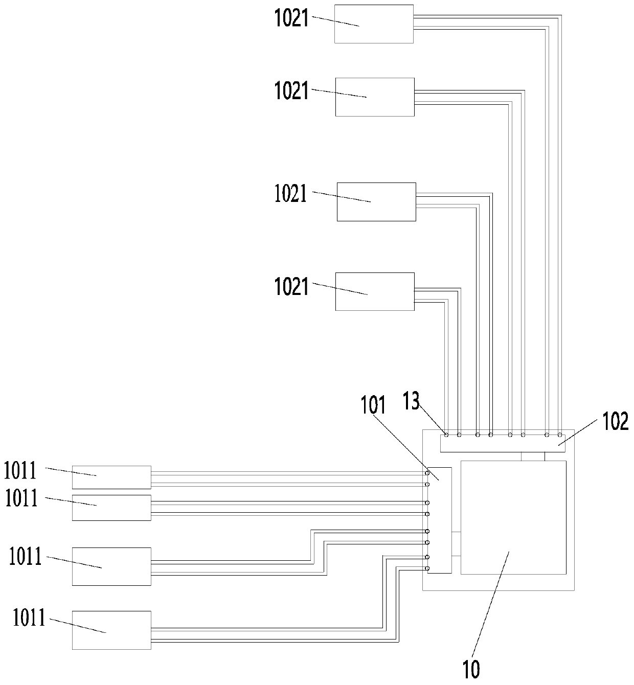
[0090]like Figure 3e As shown, in the first type of energy storage station 10, the energy absorbing end 101 is a first heat exchange device, which communicates with the heat exchange device on the side of the temperature adjustment equipment through a set of communication pipelines. The energy releasing end 102 is a second heat exchanging device, which communicates with the heat exchanging device on the side of the temperature adjustment equipment through a set of communication pipelines. That is, the pipelines at the energy absorbing end 101 and the pipelines at the energy releasing end 102 are set independently. That is, the energy absorbing end 101 of the first type of energy storage station 10 is a first heat exchange device with a set of independent communication pipelines, and the energy release end 102 is a second heat exchange device with a set of independent communication pipelines Group, used to communicate with the heat exchange device on the side of the temperature adjustment equipment.
[0091] like Figure 3f As shown, in the second type of energy storage station 10, the energy absorbing end 101 is a plurality of first heat exchange devices, through a group of connecting pipeline groups (consisting of a liquid inlet transfer pipeline 151 and a liquid outlet transfer pipeline 152) and a regulating The heat exchange device on the side of the warm equipment is connected. The energy releasing end 102 is a plurality of second heat exchanging devices, which communicate with the heat exchanging devices on the side of the temperature adjustment equipment through a set of connecting pipelines (consisting of a liquid inlet transfer pipeline 151 and a liquid outlet transfer pipeline 152). That is, the pipelines of the multiple energy absorbing ends 101 are connected to each other, and the pipelines of the multiple energy releasing ends 102 are connected to each other. That is to say, there are multiple energy absorbing ends 101 of the second type of energy storage station 10, and the liquid inlet pipes and liquid outlet pipes of the multiple energy absorbing ends communicate with each other, and the heat exchange device on the side of the temperature adjustment equipment through a set of communication pipeline groups connected. There are multiple energy release ends 102, and the liquid inlet pipes and liquid outlet pipes of the multiple energy release ends communicate with each other, and communicate with the heat exchange device on the side of the temperature adjustment equipment through a set of communication pipelines.
[0092] like Figure 3a and Figure 3c As shown, in the third type of energy storage station 10, the energy absorption end 101 is a first heat exchange device, which communicates with the heat exchange device on the side of the temperature adjustment equipment through multiple sets of communication pipeline groups. The energy releasing end 102 is a second heat exchanging device, which communicates with the heat exchanging device on the side of the temperature adjustment equipment through multiple sets of communication pipeline groups. A plurality of connecting pipeline groups of an energy absorbing end 101 are independently arranged, and a plurality of connecting pipeline groups of an energy releasing end 102 are independently arranged. That is, the third type of energy storage station 10 has one energy absorbing end 101 with multiple sets of independently arranged connecting pipeline groups, and one energy releasing end 102 with multiple sets of independently arranged connecting pipeline sets.
[0093] like Figure 3d As shown, in the fourth type of energy storage station 10, the energy absorbing end 101 is a plurality of first heat exchange devices, and the communication pipeline group 14 formed by each heat exchange device's respective liquid inlet pipe 141 and liquid outlet pipe 142 is connected with the regulator. The heat exchange device on the side of the warm equipment is connected. The energy releasing end 102 is a plurality of second heat exchanging devices, and communicates with the heat exchanging device on the side of the temperature adjustment equipment through the communication pipeline group 14 formed by the liquid inlet pipe 141 and the liquid outlet pipe 142 of each heat exchanging device. The connecting pipeline group of each energy absorbing end 101 is set independently, and the connecting pipeline group of each energy releasing end 102 is independently set. That is, there are multiple energy absorbing ends 101 of the fourth type of energy storage station, and the connecting pipeline groups of each energy absorbing end 101 are set independently; there are multiple energy releasing ends 102 of the energy storage station, and each energy releasing end 102 The connecting pipe groups of the connected pipes are set independently.
[0094] Of course, the arrangement of the energy absorbing end 101 and the energy releasing end 102 of the energy storage station 10 may be different. The specific setting methods to be used can be combined and determined according to the situation, and will not be repeated here.
[0095] In an optional embodiment, the energy storage station 10 further includes a plurality of flow control devices 13 , and the plurality of flow control devices 13 are respectively arranged on the pipelines of the energy absorption end 101 and the energy release end 102 of the energy storage station 10 . The flow control device has the function of regulating flow, including power function and throttling function. Among them, the power action is used to increase the flow, and the throttling action is used to reduce the flow. In the embodiment in which fluid medium is used for energy exchange, the flow control device may be a power pump and a solenoid valve, or an expansion valve or the like. The energy absorbing end 101 and the energy releasing end 102 of the energy storage station 10 carry out energy exchange with the external temperature regulating equipment through pipelines (inlet pipe 141 and liquid outlet pipe 142) respectively, that is, a temperature regulating equipment and the energy absorbing end 101 ( Or the energy release end 102) constitutes a medium circulation pipeline, and the flow control device can be arranged on the medium circulation pipeline corresponding to each temperature adjustment device. Through the setting of the flow control device, the flow of the medium in the respective medium circulation pipelines can be controlled and adjusted, and can be adjusted from zero to the maximum flow, so as to control the energy storage or release of the energy storage station 10 . In a specific embodiment, the flow control device is respectively arranged at the interface of each liquid inlet pipe 141 and each liquid outlet pipe 142 of the energy absorbing end 101, and each liquid inlet pipe 141 and each liquid outlet pipe of the energy releasing end 102. The interface of the tube 142.
[0096] In the embodiment of the present invention, a specific structure of the energy storage station 10 is provided, such as Figure 3g As shown, it includes one or more energy storage stacks 100, and each energy storage stack 100 includes an energy storage unit 110 for storing energy; an absorption end heat exchange device 101, and the absorption end heat exchange device is embedded in the In the energy storage stack 110 ; the release end heat exchange device 102 , the release end heat exchange device is embedded in the energy storage stack 110 .
[0097] In the embodiment of the present invention, the energy storage unit 110 can use existing energy storage materials, such as molten salt, which can store heat. There are many types of molten salts, such as ceramic matrix molten salts. Another example is an ice pack, which can store cold energy. The shape of the energy storage unit is not limited, it can be determined according to the physical properties of the energy storage material itself. For example, when molten salt is used, the energy storage unit adopts a steel shell, and the molten salt is encapsulated in the steel shell, and the steel shell Grooves are formed on the body for embedding the heat exchange device at the absorption end and the heat exchange device at the release end.
[0098] The heat exchange device at the absorption end, that is, the energy absorption end 101, one or more heat exchange devices at the absorption end can be installed in each energy storage stack. The communication pipelines of the absorption end heat exchange devices in multiple energy storage stacks can be set independently or communicate with each other. Just refer to the foregoing.
[0099] The heat exchange device at the release end, that is, the energy release end 102, one or more heat exchange devices at the release end may be installed in each energy storage stack. The communication pipelines of the discharge end heat exchange devices in multiple energy storage stacks can be set independently or communicate with each other. Just refer to the foregoing.
[0100] Of course, the energy storage station 10 also includes a heat-insulating shell, which plays a role of heat-insulation and heat-insulation to prevent energy loss.
[0101] In this embodiment, the heat exchange device at the absorption end adopts the first heat exchange coil; the heat exchange device at the discharge end adopts the second heat exchange coil. The use of coil tubes can increase the heat exchange area with the heat storage unit and improve the efficiency of storage or release.
[0102] Further, the first heat exchange coils and the second heat exchange coils are arranged alternately in the energy storage unit.
[0103] When there is only one energy storage stack 100 in the energy storage station 10 of this embodiment, the connecting pipelines of the heat exchange device 101 at the absorption end and the heat exchange device 102 at the release end adopt the aforementioned first to fourth energy storage stations 10 Just the structure.
[0104] When there are multiple energy storage stacks 100 in the energy storage station 10 of this embodiment, the communication pipelines of the heat exchange device 101 at the absorption end and the heat exchange device 102 at the release end in each energy storage stack 100 are as follows: Figure 3e or Figure 3f shown in the setup method. And add a total liquid inlet pipe and a total liquid outlet pipe at the end of the heat exchange device 101 at the absorption end, the liquid inlet pipe (141 or 151) of each absorption end heat exchange device 101 is connected to the total liquid inlet pipe, each absorption end The liquid outlet pipe (142 or 152) of the heat exchange device 101 is connected to the main liquid outlet pipe. Similarly, a total liquid inlet pipe and a total liquid outlet pipe are also added at the end of the heat exchange device 102 at the release end, and the liquid inlet pipe (141 or 151) of each heat exchange device 102 at the release end is connected to the total liquid inlet pipe. The liquid outlet pipe (142 or 152) of each discharge end heat exchange device 102 is connected to the main liquid outlet pipe.
[0105] combine Figure 4a to Figure 4f As shown, a kind of intermediate transfer heat exchanger of the present invention is described, which is denoted as the first intermediate transfer heat exchanger 20, and includes: a heat absorbing end 201, which is used to communicate with the energy storage station 10/temperature adjustment equipment (such as the first temperature adjustment device 1111 or fourth temperature regulation device 1221); and, the heat release terminal 202 is used to communicate with a temperature regulation device (eg, second temperature regulation device 1121 or third temperature regulation device 1211)/energy storage station 10.
[0106] The first intermediate transfer heat exchanger 20 of the embodiment of the present invention is connected between the energy storage station 10 and the temperature adjustment equipment, and plays a role in transferring energy between the energy storage station 10 and multiple temperature adjustment equipment. In actual application, the number of temperature adjustment equipment is indeterminate, it can be one, or two, or even more; and the energy storage station 10 can also have one or more. Therefore, the intermediate conversion heat in the embodiment of the present invention There are one or more heat-absorbing ends 201 of the device, and one or more heat-dissipating ends 202, so that one channel can be converted to multiple channels, multiple channels can be converted to one channel, or multiple channels can be converted to multiple channels. The storage and release of energy between temperature equipment (absorption end temperature adjustment equipment 1011 or release end temperature adjustment equipment 1021), and the path control is convenient. According to the actual situation, some of the paths can be turned on for energy exchange. Moreover, it can also simplify the communication pipeline between the energy storage station and the temperature adjustment equipment, facilitate the layout of the pipeline, and reduce the cost.
[0107] In the intermediate transfer heat exchanger 20 of the embodiment of the present invention, when the heat absorption end 201 is connected to the energy storage station 10, the heat release end 202 is connected to the temperature adjustment equipment, and the energy storage station 10 supplies heat to the temperature adjustment equipment through the intermediate transfer heat exchanger 20 , it may also be that the temperature regulation equipment supplies cold energy to the energy storage station through the intermediate heat exchanger 20 . When the heat-absorbing end 201 is connected to the temperature-regulating device, the heat-discharging end 202 is connected to the energy storage station 10, and the temperature-regulating device supplies heat to the energy storage station 10, or the energy storage station 10 supplies cold energy to the temperature-regulating device.
[0108] In the embodiment of the present invention, the heat-absorbing end 201 is used to absorb the heat of the energy storage station 10 (or, the first temperature adjustment device 1111 ), that is, the cold-discharging end (release cold). The concrete structure that adopts is various, as, utilize fluid medium as carrier, heat-absorbing end 201 adopts heat-exchanging device and the heat-exchanging device of heat releasing end 112 (or, the first temperature-regulating equipment 1111) of side of heat storage station 11 through pipeline In communication, the fluid medium absorbs the heat on the side of the heat storage station 11 (or, the first temperature adjustment device 1111), the fluid medium flows to the heat-absorbing end 201, and the medium fluid in the heat-absorbing end 201 and the heat-discharging end 202 performs heat exchange, thereby The heat is transferred to the exothermic end 202 . Alternatively, the heat-absorbing end 201 communicates with the heat-exchanging device of the cold-energy absorbing end 121 (or the fourth temperature-regulating device 1221 ) of the cold-energy storage station 12 through a pipeline through a heat exchange device. At this time, the heat-absorbing end 201 can understand In order to release the cold end 201, the fluid medium absorbs the heat on the side of the cold storage station 12 (or, the fourth temperature adjustment device 1221) (absorbs heat, that is, releases cold), and the fluid medium flows to the heat-absorbing end 201 to absorb heat. The end 201 exchanges heat with the medium fluid at the heat release end 202 , thereby transferring heat to the heat release end 202 .
[0109] Similarly, the heat release end 202 is used to release heat to the energy storage station 10 (or, the second temperature adjustment device 1121 ), that is, the end for absorbing cold (absorbing cold). The concrete structure that adopts is various, as, utilize fluid medium as carrier, heat releasing end 202 adopts heat exchanging device and the heat exchanging device of heat absorbing end 111 (or, the second temperature regulating equipment 1121) of heat storage station 11 side through pipeline connected, the fluid medium absorbs the heat on the side of the heat storage station 11 (or, the second temperature adjustment device 1121), the fluid medium flows to the heat release end 202, and the heat release end 202 exchanges heat with the medium fluid at the heat absorption end 201, thereby The heat is transferred to the heat-absorbing end 201 . Alternatively, the heat release end 202 uses a heat exchange device to communicate with the heat exchange device of the cold energy release end 122 (or the third temperature adjustment device 1211) of the cold storage station 12 through a pipeline, and the fluid medium flows to the cold storage station 12 side. (Or, the third temperature adjustment device 1211) releases heat (releases heat, that is, absorbs cold), and the fluid medium flows to the heat release end 202, and the heat release end 202 exchanges heat with the medium fluid at the heat absorption end 201, thereby converting The heat is transferred to the heat sink 201 .
[0110] That is, when the intermediate transfer heat exchanger is applied to the cold storage device, the inverse process of heat transfer in the intermediate transfer heat exchanger 20 is cold transfer, that is, heat is absorbed and cold is released.
[0111] In an optional embodiment, the heat absorption end 201 specifically adopts a heat exchange device, such as a plate heat exchanger, an evaporator, or a heat exchange coil. The heat release end 202 specifically adopts a heat exchange device, such as a plate heat exchanger, a condenser, or a heat exchange coil.
[0112] In the first intermediate conversion heat exchanger 20 of the embodiment of the present invention, the number of heat-absorbing ends 201 and heat-discharging ends 202, and the setting of the externally connected connecting pipeline groups of the heat-absorbing ends 201 and heat-discharging ends 202 are determined according to the number of connecting sides (Energy storage station side and temperature adjustment equipment side) The number of connecting pipeline groups of the heat exchange device (please refer to the content about the energy storage device below) can be determined.
[0113] In an optional embodiment, there are one or more heat absorption ends 201 of the first intermediate transfer heat exchanger 20 in the embodiment of the present invention, and the pipeline of each heat absorption end 201 is set independently. For example, the heat sink 201 includes a (such as Figure 4a , Figure 4b and Figure 4f shown) or multiple (see Figure 4d The heat release end 202 of the intermediate transfer heat exchanger 20) the third heat exchange device, each third heat exchange device has a liquid inlet pipe 211 and a liquid outlet pipe 212 (that is, a group of communication pipeline groups 21), through two A pipeline communicates with the heat exchange device on the side of the energy storage station 10 (or, the first temperature regulation device 1111 or the fourth temperature regulation device 1221), and uses a fluid medium to connect the energy storage station 10 (or, the first temperature regulation device 1111 or The heat on the side of the fourth temperature regulating device 1221) is transferred to the heat-absorbing end 201. That is, each third heat exchange device is independently communicated with the energy storage station 10 (or, the first temperature adjustment device 1111 or the fourth temperature adjustment device 1221 ). Another example, such as Figure 4c , Figure 4e As shown, the heat absorbing end 201 is a third heat exchange device, and the liquid inlet end of the third heat exchange device is connected to a plurality of liquid inlet pipes 211 , and the liquid outlet end is connected to a plurality of liquid outlet pipes 212 . A liquid inlet pipe 211 and a liquid outlet pipe 222 are used as a connecting pipeline group 21 to form a plurality of independent communicating pipeline groups, through which the multiple independent communicating pipeline groups respectively exchange heat with the third external temperature adjustment equipment side. The device is connected.
[0114] In another optional embodiment, there are multiple heat-absorbing ends 201 , and the pipelines of the multiple heat-absorbing ends 201 communicate with each other. There are many ways to communicate with each other, as long as multiple heat sinks can communicate with the energy storage station 10 (or, the first temperature regulation device 1111 or the fourth temperature regulation device 1221 ). For example, if Figure 4d As shown, a plurality of heat-absorbing ends 201 are communicated through a liquid inlet transfer pipeline 221 and a liquid outlet transfer pipeline 222, and the liquid inlet pipe 211 of each heat-absorbing end 201 is communicated with the liquid inlet transfer pipeline 221, and each heat-absorbing end The liquid outlet pipes 212 at the end 201 are all in communication with the liquid outlet transfer pipeline 222 . Then through the liquid inlet transfer pipeline 221 and the liquid outlet transfer pipeline 222 as a group of connected pipeline groups, through two pipelines and the energy storage station 10 (or, the first temperature adjustment device 1111 or the fourth temperature adjustment device 1221) The heat exchange device on the side is connected.
[0115] Similarly, when there are one or more heat-dissipating ends 202, the pipelines of each heat-dissipating end 202 are independently arranged, and the setting method is the same as that of the aforementioned heat-absorbing end 201. When there are multiple heat releasing ends 202 , the pipelines of the plurality of heat releasing ends 202 are connected to each other, and the communication method is the same as that of the aforementioned heat absorbing ends 201 . I won't repeat them here.
[0116] Therefore, in the first intermediate transfer heat exchanger according to the embodiment of the present invention, according to the arrangement of the pipelines at the heat absorption end 201 and the heat exchange end 202 , there are several specific embodiments as follows.
[0117] like Figure 4a As shown, in the first intermediate transfer heat exchanger I, there is one heat-absorbing end 201 with one connecting pipeline group; there are multiple heat-discharging ends 202, and the communicating pipeline groups of the multiple heat-releasing ends 202 are set independently. That is, the pipelines of the heat-absorbing end 201 and the heat-discharging end 202 are provided independently. All the way to multiple roads.
[0118] like Figure 4b As shown, the first intermediate transfer heat exchanger II has one heat absorbing end 201 and a set of connecting pipelines; one heat releasing end 202, and one heat releasing end 202 has multiple independently set connecting pipeline groups. That is, the pipelines of the heat-absorbing end 201 and the heat-discharging end 202 are provided independently. All the way to multiple roads.
[0119] like Figure 4c As shown, in the first intermediate conversion heat exchanger III, there is one heat absorbing end 201, and one heat absorbing end 201 has a plurality of independently arranged communicating pipeline groups; one heat releasing end 202 has one communicating pipeline group. That is, the pipelines of the heat-absorbing end 201 and the heat-discharging end 202 are provided independently. Multi-way turn all the way.
[0120] like Figure 4d As shown, in the first intermediate conversion heat exchanger V, there are multiple heat-absorbing ends 201, and the multiple heat-absorbing ends 201 are connected to each other by a group of connecting tube groups and the heat exchanger on the side of the energy storage station 10 (or the temperature-regulating device 1011 at the absorption end). The heat device is connected; there are multiple heat release ends 202, and the communication pipeline groups of the multiple heat release ends 202 are set independently. That is, the pipelines of the plurality of heat-absorbing ends 201 are connected to each other, and the pipelines of the plurality of heat-dissipating ends 202 are independently arranged. All the way to multiple roads.
[0121] like Figure 4e As shown, in the first intermediate conversion heat exchanger IV, there is one heat-absorbing end 201, and one heat-absorbing end 201 has a plurality of independently arranged communication pipeline groups; Connected pipeline group set. That is, the pipelines of the heat-absorbing end 201 and the heat-discharging end 202 are provided independently. Multi-way to multi-way.
[0122] like Figure 4f As shown, the first intermediate transfer heat exchanger VI has one heat absorbing end 201 and a set of connecting pipelines; one heat releasing end 202 has a set of connecting pipelines. That is, the pipelines of the heat-absorbing end 201 and the heat-discharging end 202 are provided independently. All the way around.
[0123] Of course, the structure of the first intermediate heat exchanger in the embodiment of the present invention is not limited to the above six types, and the structures of the heat-absorbing end 201 and the heat-discharging end 202 can be interchanged or combined arbitrarily. The number of communication pipeline groups of the heat exchange device on the communication side (the side of the energy storage station and the side of the temperature adjustment equipment) only needs to determine the structure of the adapted intermediate transfer heat exchanger. In addition, when there are multiple groups of communication pipelines at the heat absorbing end 201 (or heat releasing end 202) of the first intermediate conversion heat exchanger, the number is not limited, depending on the energy storage station 10 or temperature adjustment equipment that needs to be connected The number can be determined.
[0124] In the first intermediate transfer heat exchanger 20 of the embodiment of the present invention, the heat exchange device at the heat absorption end 201 and the heat exchange device at the heat release end 202 can be arranged separately, for example, when a plate heat exchanger is used, the two are arranged oppositely (can Contact or non-contact) to ensure the maximum heat exchange area; when using heat exchange coils, the coil parts of the two are arranged alternately (contact or non-contact) to ensure effective heat exchange. Alternatively, the heat exchange device at the heat absorption end 201 and the heat exchange device at the heat release end 202 are designed as one. The arrangement method is not limited, as long as the heat exchange device at the heat absorption end 201 and the heat exchange device at the heat release end 202 can conduct heat transfer. like Figure 4a to Figure 4f As shown, both the heat-absorbing end 201 and the heat-discharging end 202 adopt a non-contact heat exchange device structure. Of course, the first intermediate heat transfer device in the embodiment of the present invention is not limited to the structure shown in the drawings.
[0125] In an optional embodiment, the intermediate transfer heat exchanger 20 further includes a heat absorption valve 231, which is arranged in series on the pipeline of the heat absorption end 201; and/or, a heat release valve 232, which is arranged in series at the heat release end 202 on the pipeline. The purpose of setting the valve is to control the opening or closing of the heat absorbing end 201 and the heat releasing end 202 . In a specific embodiment, a heat absorption valve 231 is arranged on the liquid inlet pipe and the liquid outlet pipe of each heat absorption end 201 (each heat exchange device), and a heat absorption valve 231 is arranged at each heat release end 202 (each heat exchange device). Both the liquid inlet pipe and the liquid outlet pipe are provided with exothermic valves 232 . Through the control of each valve, the opening and closing control of the communication pipelines of the heat release end 202 and the heat absorption end 201 of the center transfer heat exchanger 20 are respectively realized, and the energy transmission is adjusted, so that the energy storage station 10 can be controlled according to the actual situation. The energy is released to part of the temperature-regulating equipment, and the energy storage station 10 of the part of the temperature-regulating equipment can also be controlled to store energy.
[0126] combine Figure 4g and Figure 4h As shown, in the embodiment of the present invention, there is also provided an intermediate transfer heat exchanger, a second intermediate transfer heat transfer device 30, comprising: a heat absorption end 301, which is used to communicate with the energy storage station 10/temperature adjustment equipment (such as the first temperature regulation device 1111 or the fourth temperature regulation device 1221); the heat release end 302 is used to connect to the temperature regulation device (such as the second temperature regulation device 1121 or the third temperature regulation device 1211)/energy storage station 10; and, In the unidirectional heat conducting device 31 , the heat absorbing end 301 and the heat releasing end 302 are arranged at both ends of the unidirectional heat conducting device 31 .
[0127] The second intermediate conversion heat exchanger 30 of the embodiment of the present invention can provide precise energy for the temperature regulation equipment when the energy storage station releases energy to the temperature regulation equipment at the release end by adding a unidirectional heat conduction device 31 . In addition, it is also applicable to the situation that energy transmission cannot be performed in the set direction between the energy storage station 10 and the temperature regulation equipment (the temperature regulation equipment 1011 at the absorption end or the temperature regulation equipment 1021 at the release end). Generally, when heat is transferred, it can only be transferred from the high temperature end to the low temperature end. If the temperature in the heat storage station itself is higher than the temperature of the medium output by the temperature adjustment equipment, at this time, the heat storage station still has a lot of heat to supply If the storage capacity is too large, the heat storage station cannot be stored in the set direction at this time, but it will cause the heat loss of the heat storage station, which has the opposite effect. When the heat storage station releases heat, it will also encounter the same problem. Therefore the embodiment of the present invention provides this second intermediate conversion heat exchanger 30, utilizes unidirectional heat conduction device 31 to lead to the medium temperature of heat (cooling capacity) storage station from temperature adjustment equipment, and guides equipment from heat (cooling capacity) storage station The temperature of the medium is adjusted so that it can provide accurate energy to the temperature regulating device at the release end, or make the energy storage station 10 and the temperature regulating device normally carry out heat transfer according to the set direction.
[0128] The second intermediate transfer heat exchanger 30 of the embodiment of the present invention is based on the aforementioned first intermediate transfer heat transfer device 20 , and a unidirectional heat conduction device 31 is added between the heat-absorbing end and the heat-discharging end. Therefore, the structural arrangement of the absorbing end 301 and the heat releasing end 302 of the second intermediate heat exchanger 30, and the functions played are the same as those of the heat absorbing end 201 and the heat releasing end 202 of the first intermediate heat exchanger 20, which can be referred to The aforementioned content will not be repeated here.
[0129] Therefore, according to Figure 4a to Figure 4f In the structure of the first intermediate transfer heat exchanger I to the first intermediate transfer heat transfer device VI, a one-way heat conduction device 31 is added between the heat absorption end and the heat release end to obtain the heat absorption end and the heat release end in sequence. The second intermediate heat exchanger I to the second intermediate heat exchanger VI. like Figure 4g The shown second intermediate heat exchanger II30 is obtained by adding a one-way heat conduction device 31 on the basis of the first intermediate heat exchanger II20, as Figure 4h The shown second intermediate heat exchanger VI30 is obtained by adding a unidirectional heat conduction device 31 on the basis of the first intermediate heat exchanger VI20.
[0130] In the second intermediate transfer heat exchanger 30 of the embodiment of the present invention, the unidirectional heat conduction device 31 realizes (forced) exchange of heat from the heat-absorbing end to the heat-dissipating end. Specifically, a refrigerant heat exchanger or a semiconductor temperature regulator can be used.
[0131] In an optional embodiment, the refrigerant heat exchanger includes an evaporator 311, a compressor (not shown in the figure), a condenser 312 and an expansion valve (not shown in the figure), and the four are connected to form a heat exchange circuit. The second intermediate heat transfer device 30 includes two heat-insulating heat-absorbing chambers 303 and heat release chambers 304; In the chamber 303 ; the condenser 312 is arranged opposite to the heat release end 302 of the second intermediate transfer heat exchanger 30 , and is arranged in the heat release chamber 304 .
[0132]In another optional embodiment, the semiconductor temperature regulator includes a semiconductor cooling sheet, a first-end heat exchanger arranged at the first end of the semiconductor cooling sheet, a second-end heat exchanger at the second end, and a power supply device. The power supply device is used to provide electric energy for the semiconductor refrigeration sheet. By controlling the direction of the power supply current, the first end and the second end of the semiconductive refrigerating sheet can be switched between two modes of heat generation and cold generation. For example, under forward current, the first terminal is the cold terminal, and the second terminal is the hot terminal; after switching the direction of the current, the first terminal is switched to the hot terminal, and the second terminal is switched to the cold terminal. The second intermediate heat exchanger 30 includes two heat-insulating chambers 303 and heat releasing chambers 304; In the heat-absorbing chamber 303 ; the second-end heat exchanger is arranged opposite to the heat-discharging end 302 of the second intermediate transfer heat exchanger 30 , and is disposed in the heat-discharging chamber 304 . It is enough to determine that the heat exchanger at the first end is the hot end (or cold end) and the heat exchanger at the second end is the cold end (or hot end) according to the actual situation.
[0133] When it is necessary to provide accurate energy to the temperature regulation equipment at the release end, or when the heat transfer cannot be carried out in the set direction between the energy storage station 10 and the temperature regulation equipment, the one-way heat conduction device 31 is started to transfer the heat from the heat absorption end 301 Forced exchange to the heat release end 302, and then the heat is transferred from the heat release end 302 to the energy storage station 10 (or the temperature adjustment device 1011 at the absorption end, or the temperature adjustment device 1021 at the release end).
[0134] The intermediate conversion heat exchanger is used to divide the energy released from the energy storage station. The mixing unit neutralizes the energy split by multiple intermediate conversion heat exchangers to obtain the set energy, and then the mixing unit outputs the set energy to the device. The fixed energy matches the temperature regulation equipment side. The matching energy can be accurately provided to the temperature regulating equipment at the release end of the energy release end of the energy storage station. In particular, a medium of matched temperature may be provided.
[0135] In the embodiment of the present invention, the role of the mixing unit 41 is to mix media with different energies (temperatures) to obtain a media with a set energy (set temperature), and then output the media to the temperature adjustment device (release end temperature adjustment) device 1021) side. Therefore, in a specific embodiment, such as Figure 5a and Figure 5b As shown, the mixing unit 41 has two separate chambers, one liquid inlet chamber 411, and the other is a liquid return chamber 412, the liquid inlet chamber 411 has one or more input liquid inlet pipes 4111, and one or more One output and outlet pipe 4112; the liquid return chamber 412 has one or more input and outlet pipes 4122, and one or more output and inlet pipes 4121. An input liquid inlet pipe 4111 and an input liquid outlet pipe 4122 form an input end connecting pipeline group, and an output liquid inlet pipe 4121 and an output liquid outlet pipe 4112 form an output end connecting pipeline group. An input-end connecting pipeline group communicates with an output-end pipeline group of the intermediate transfer heat exchanger, and an output-end pipeline group communicates with the terminal heat exchange device on the side of the temperature adjustment equipment. The mixing unit 41 has two or more sets of communication pipelines at the input end, which are used to communicate with the communication pipelines of the first energy output ends of two or more intermediate transfer heat exchangers. The output end of the mixing unit 41 may be connected to one or more sets of pipelines, and in one set, it is only connected to the terminal heat exchange device of one temperature regulating device. When there are multiple groups, they are respectively connected with the terminal heat exchange devices of multiple temperature adjustment equipments to provide energy for multiple temperature adjustment equipments. Moreover, at this time, switch valves are set on the connecting pipeline groups at each output end to facilitate the communication of the control part. The opening and closing of pipelines can provide energy for one or more temperature control equipment.
Login to view more PUM


Description & Claims & Application Information
We can also present the details of the Description, Claims and Application information to help users get a comprehensive understanding of the technical details of the patent, such as background art, summary of invention, brief description of drawings, description of embodiments, and other original content. On the other hand, users can also determine the specific scope of protection of the technology through the list of claims; as well as understand the changes in the life cycle of the technology with the presentation of the patent timeline. Login to view more.
Login to view more Similar technology patents
Control method of energy system
InactiveCN109764558AReduce energy consumption and wasteEnergy recovery in ventilation and heatingFluid heatersEvaporatorEngineering
Owner:QINGDAO HAIER AIR CONDITIONER GENERAL CORP LTD
Control method of energy system
ActiveCN109764453AReduce energy consumption and wasteEnergy recovery in ventilation and heatingMechanical apparatusProcess engineeringWater tanks
Owner:QINGDAO HAIER AIR CONDITIONER GENERAL CORP LTD +1
Surplus wind energy heating system
PendingCN111425925ASolve the waste of surplus wind energyReduce energy consumption and wasteMachines/enginesWind motor combinationsHeating systemElectric generator
Owner:中如实业(上海)有限公司
Energy system, control method of energy system and storage medium
ActiveCN109764513AReduce energy consumption and wasteEnergy recovery in ventilation and heatingDomestic cooling apparatusProcess engineeringEvaporator
Owner:QINGDAO HAIER AIR CONDITIONER GENERAL CORP LTD +1
Energy system as well as control method of bed body temperature adjustment of energy system
Owner:QINGDAO HAIER AIR CONDITIONER GENERAL CORP LTD
Classification and recommendation of technical efficacy words
- Reduce energy consumption and waste
Efficient aluminum ash separating agent
ActiveCN105002365AHigh recovery rateReduce energy consumption and wasteSeparating agentEnvironmentally friendly
Owner:博众优浦(常熟)汽车部件科技有限公司
Energy system and heater temperature adjusting control method thereof
ActiveCN109764397AReduce energy consumption and wasteCentral heating with accumulated heatLighting and heating apparatusHeat outputIntermediate heat exchanger
Owner:QINGDAO HAIER AIR CONDITIONER GENERAL CORP LTD +1
Control method of energy system
ActiveCN109764507AReduce energy consumption and wasteEnergy recovery in ventilation and heatingFluid heatersProcess engineeringEnergy consumption
Owner:QINGDAO HAIER AIR CONDITIONER GENERAL CORP LTD +1
Control method of electric temperature control mattress
Owner:QINGDAO HAIER AIR CONDITIONER GENERAL CORP LTD
Control method of energy system
ActiveCN109855345AReduce energy consumption and wasteLighting and heating apparatusDomestic refrigeratorsCool storageProcess engineering
Owner:CHONGQING HAIER AIR CONDITIONER CO LTD +2