Tension measuring device and tensiometer auxiliary clamping tool thereof

A technology of measuring device and clamping tool, applied in tension measurement and other directions, which can solve the problems of easy shaking of operators and inaccurate tension measurement.

Pending Publication Date: 2019-06-07
HENAN PROVINCE INST OF METROLOGY
0 Cites 2 Cited by

AI-Extracted Technical Summary

Problems solved by technology

[0004] The purpose of the present invention is to provide a tension measurement device to solve the problem in the prior art that the operator is prone to shaking during tension measu...

Abstract

The invention relates to a tension measuring device and a tensiometer auxiliary clamping tool thereof. The tension measuring device comprises a tensiometer and a tensiometer auxiliary clamping tool; the tensiometer auxiliary clamping tool comprises a device seat; the device seat is rotatably provide with a measuring bracket; the measuring bracket is provided with a lateral moving bracket in a guided moveable manner; the lateral moving bracket is provided with a longitudinal moving bracket in a guided moveable manner; the lateral moving bracket is provided with a longitudinal moving bracket driving mechanism for driving the longitudinal moving bracket to reciprocate; and the axial direction of the measuring bracket, the moving direction of the lateral moving bracket and the moving directionof the longitudinal moving bracket are perpendicular to one another; the tensiometer is fixed on the longitudinal moving bracket; and the moving direction of a measuring rod is consistent with the axial direction of the measuring bracket. With the tension measuring device and the tensiometer auxiliary clamping tool thereof of the invention adopted, the problem of inaccurate tension measurement caused by a condition that an operator tends to shake during tension measurement in the prior art can be solved.

Application Domain

Tension measurement

Technology Topic

Lateral moveEngineering +1

Image

  • Tension measuring device and tensiometer auxiliary clamping tool thereof
  • Tension measuring device and tensiometer auxiliary clamping tool thereof
  • Tension measuring device and tensiometer auxiliary clamping tool thereof

Examples

  • Experimental program(1)

Example Embodiment

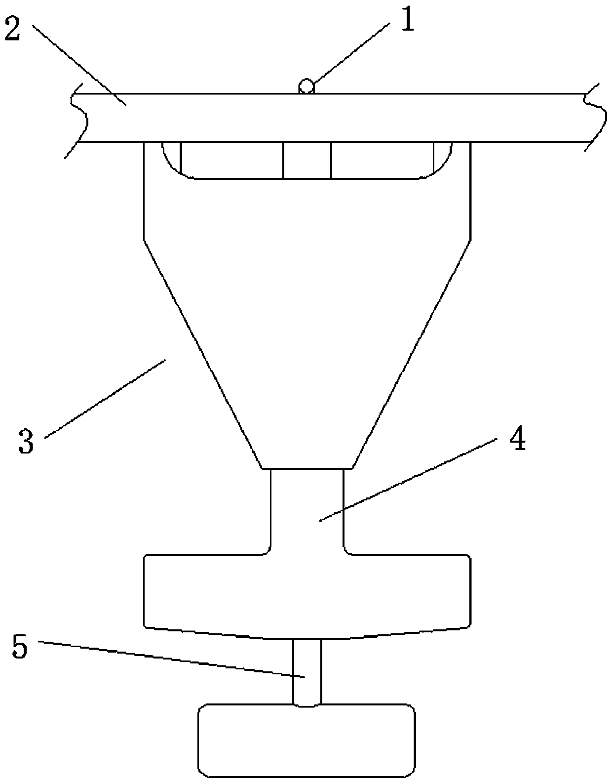
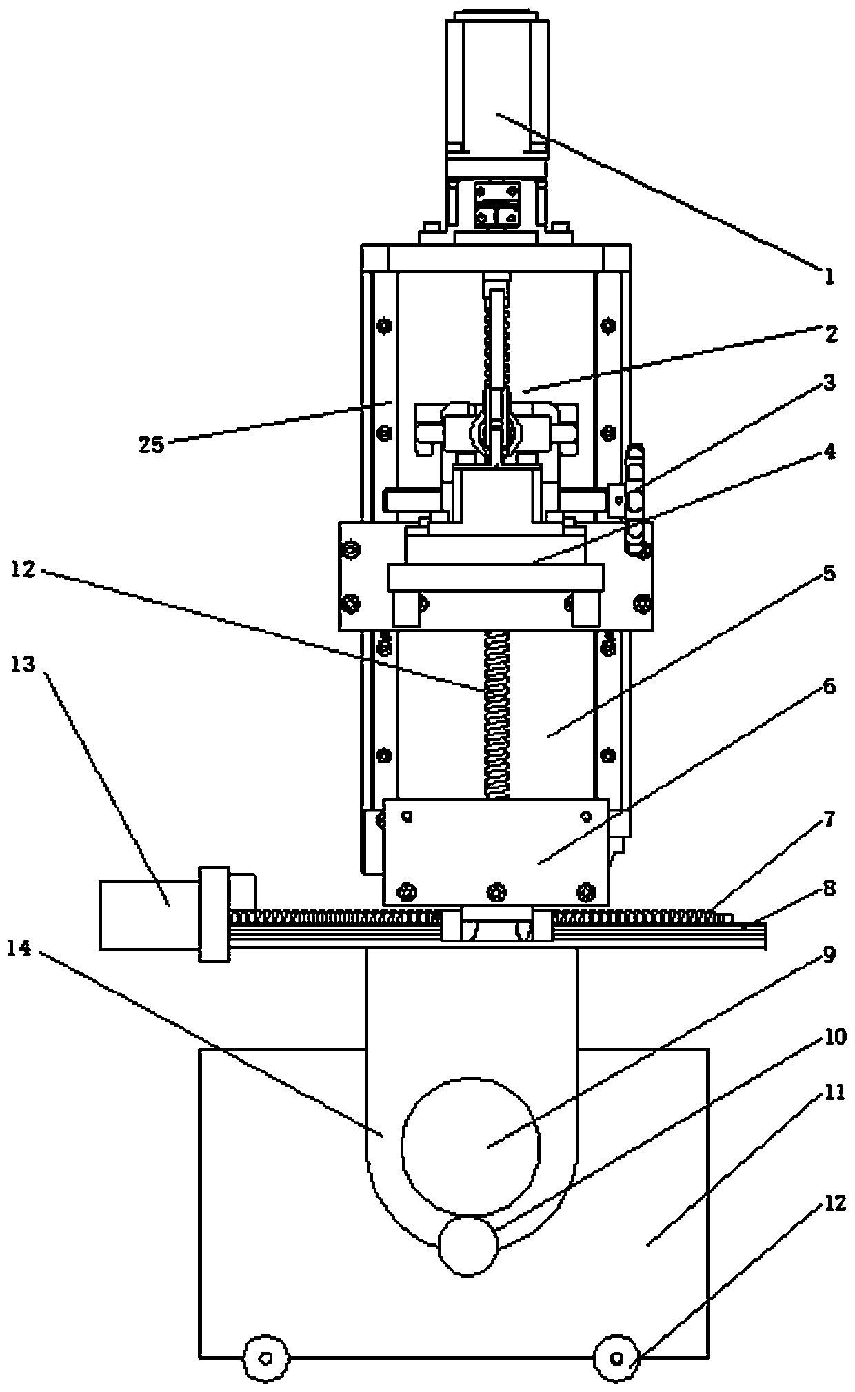
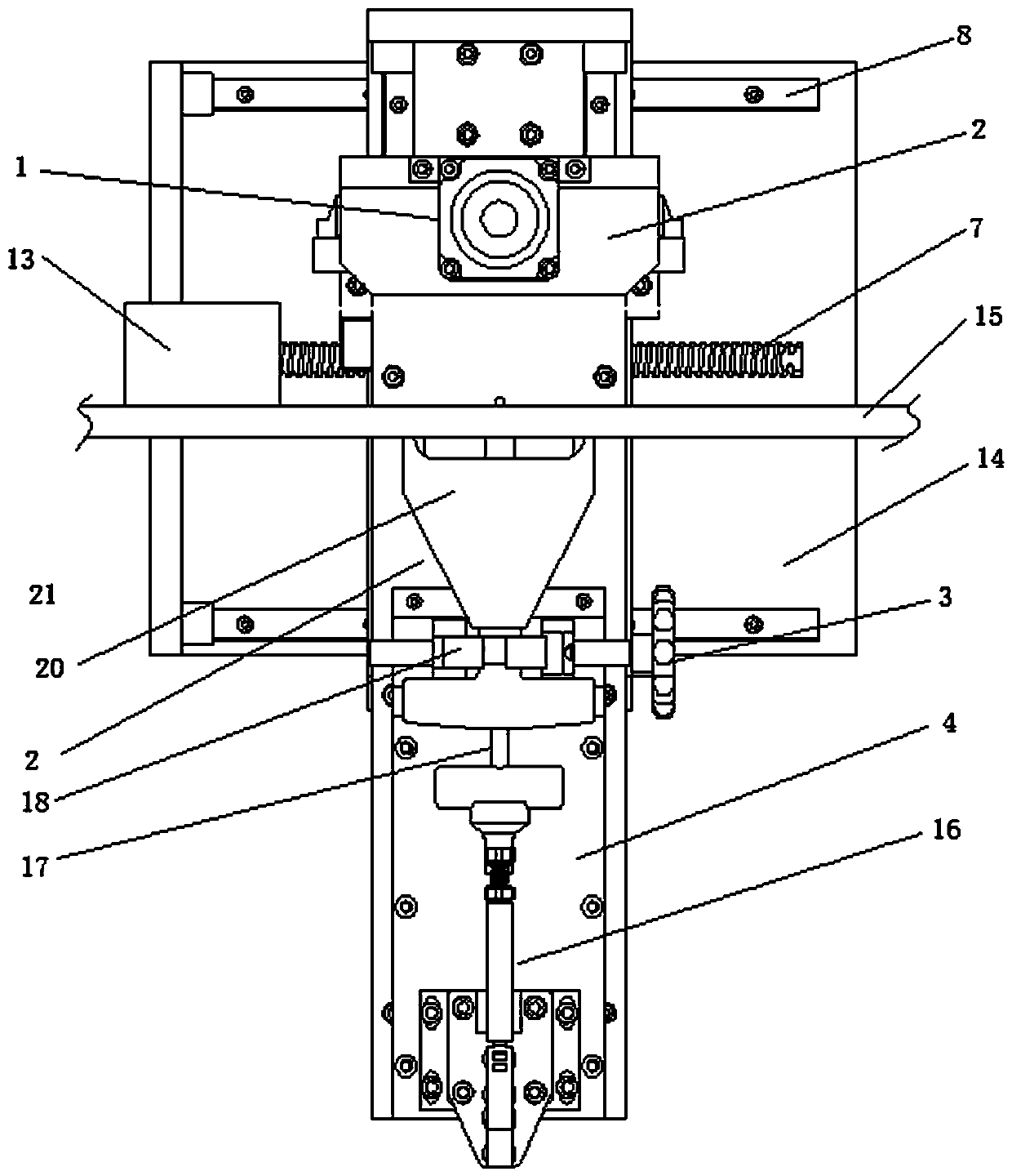
[0023] An example of a tension measuring device is Figure 2~6 Shown: comprise tensiometer 2 and tensiometer auxiliary clamping tool, wherein tensiometer belongs to prior art, and it comprises tensiometer housing 20 and guiding movement is assembled on the measuring bar 17 on the tensiometer housing, measuring bar 17 and tension A measuring rod return spring is arranged between the gauge housings 20, and a hook structure 21 for hooking a corresponding piece to be measured is arranged at the front end of the tensiometer. The innovation of the present invention lies in the design of an auxiliary tensiometer clamping tool capable of clamping and fixing the tension gauge.
[0024] The tensiometer auxiliary clamping tool includes a device seat 11. The bottom of the device seat 11 is provided with a walking wheel 12. The device seat is rotatably equipped with a measuring bracket 14 whose rotation axis extends along the front and rear directions. Support drive mechanism, in the present embodiment, support drive mechanism comprises support drive motor, and the motor shaft of support drive motor is coaxially fixed with transmission pinion 10, and the transmission bull gear that meshes transmission with transmission pinion is installed on the device seat 9. The measuring bracket 14 is fixedly connected with the transmission gear 9, so when the transmission gear rotates, the measurement bracket can be driven to rotate around the axis of the transmission gear.
[0025] The measuring support 14 is provided with a transverse guide rail 8, and the transverse guide rail is equipped with a transversely moving support 6 for guiding and moving. It includes a laterally moving bracket screw rod 7 connected to the laterally moving bracket by screw transmission and a laterally moving bracket driving motor 13 that drives the laterally moving bracket screw rod 7 to rotate. The front end of the laterally moving support has a stand 5, and the stand is provided with a vertical guide rail 25, and the vertical guide rail 25 is guided and moved to be equipped with a longitudinally moving support 4, and the longitudinally moving support 4 is a cantilever whose front end and the stand are connected by the vertical guide rail. structure, the stand is provided with a longitudinally moving stand driving mechanism that drives the longitudinally moving stand to and fro. In this embodiment, the longitudinally moving stand driving mechanism includes a longitudinally moving stand screw 12 that is threadedly connected with the longitudinally moving stand, and is arranged on the stand The vertically moving support driving motor 1 connected with the vertically moving support screw rod transmission at the top. The axis of rotation of the measuring bracket 14, the moving direction of the laterally moving bracket 6, and the moving direction of the longitudinally moving bracket 4 are perpendicular to each other, and the guiding movement direction of the measuring rod 17 of the tensiometer is along the front and rear direction, which is consistent with the axial direction of the measuring bracket.
[0026] The rear end of the longitudinally moving bracket is provided with a tensiometer detachable fixing structure for the detachable fixing of the corresponding tensiometer. In this embodiment, the detachable fixing structure includes an adjusting screw driven by the handwheel 3, and the axis of the adjusting screw is along the The direction is extended, and the detachable fixing structure also includes two clamping blocks 18 that can move oppositely and oppositely under the drive of the adjusting screw. The clamping part of the tension gauge 2 can be clamped and fixed by turning the adjusting screw, and the two clamping blocks move relatively. The rear end of the longitudinally moving support is provided with a quick clamp, and the quick clamp includes a clamp operating arm 16 for the operator to hold and operate, and is driven by the clamp operating arm 16 to apply a push force to the tail end of the measuring rod of the tensiometer. The push rod 29, the push rod 29 can apply a thrust in the forward direction to the measuring rod 17 tail end of the tensiometer, and the front end of the push rod is provided with a V-shaped positioning push groove 33 to match the arc of the measuring rod tail end. The matching relationship between the push rod and the clamp operating arm is that the push rod is hingedly connected with the clamp operating arm, the clamp operating arm is hingedly connected with the longitudinal moving bracket, and the hinge axis of the push rod is connected with the clamp operating arm. The hinge axes are set parallel to each other.
[0027] Take the cable belt 15 as an example to illustrate the use of the tension measuring device in the present invention, as Image 6 Shown: When performing on-site tension testing on the cable belt, the posture of the cable belt is often not horizontal. At this time, the measuring bracket can be rotated first. The angle at which the cable can be measured, that is, the angle at which the measuring rod of the tensiometer can hang the cable vertically, can adjust the measuring position of the tension meter to the cable by moving and adjusting the lateral movement bracket, and the operator rotates the quick clamp The clamp operating arm of the clamp, the clamp operating arm drives the push rod to push the measuring rod of the tensiometer forward, the hook structure at the front end of the measuring rod moves forward and crosses the tension measurement position of the cable belt, and then moves the bracket longitudinally to drive the motor belt Move the bracket lead screw vertically, and the vertically moving bracket moves upward with the tensiometer until the hook structure at the front end of the measuring rod of the tensiometer can hook the cable belt, and the operator turns the clamp operating arm in the opposite direction, and the push rod does not stop Then apply a thrust to the measuring rod of the tensiometer, and the measuring rod of the tensiometer resets under the action of its own return spring and pulls the cable to measure the tension of the cable.
[0028]In the process of measuring the tension of the cable, it is no longer necessary for the operator to hold the tensiometer, thus avoiding the deflection and shaking of the tensiometer caused by the defect of manual operation. The tension measuring device in the present invention can measure the tension of the cable belt, and can also select a suitable tension meter to measure the tension of the belt according to the needs. The pushing and unloading force of the measuring rod of the tensiometer can also be realized by electric means, such as setting an electric push rod that can apply thrust to the measuring rod of the tensiometer. Of course, the operation of the measuring rod can also be completely done manually. Realization, for example, the operator pushes the measuring rod to move forward; the detachable fixed structure of the tensiometer can also be a bolt-fixed structure, for example, the tensiometer is fixed on the longitudinal moving bracket by bolts, and the tensiometer can also be fixed through the non-detachable The method is fixed on the longitudinal moving bracket, for example, the tensiometer shell is directly welded and fixed on the longitudinal moving bracket; Or the drive cylinder drives a rack to move linearly, and a gear meshing with the rack is fixed on the measuring bracket. When the rack moves linearly, the measuring bracket can be driven to rotate through the gear; the movement of each moving part along the corresponding guide rail can also be achieved by Driven by the drive cylinder.
[0029] Examples of tensiometer-assisted gripping tools are Figure 2~6 Shown: the specific structure of the tensiometer auxiliary clamping tool is the same as the tensiometer auxiliary clamping tool described above in the implementation of each tension measuring device, and will not be described in detail here.

PUM

no PUM

Description & Claims & Application Information

We can also present the details of the Description, Claims and Application information to help users get a comprehensive understanding of the technical details of the patent, such as background art, summary of invention, brief description of drawings, description of embodiments, and other original content. On the other hand, users can also determine the specific scope of protection of the technology through the list of claims; as well as understand the changes in the life cycle of the technology with the presentation of the patent timeline. Login to view more.
Why Eureka
Try Eureka