Feeding device for aquaculture

A technology of aquaculture and mounting seat, which is applied in the field of feeders, can solve the problems of concentrated throwing feed, high labor intensity, and short distance of throwing feed, and achieve the effects of preventing competition, reducing labor intensity, and increasing stability

Inactive Publication Date: 2019-06-14
叶建德
View PDF10 Cites 9 Cited by
  • Summary
  • Abstract
  • Description
  • Claims
  • Application Information

AI Technical Summary

Problems solved by technology

[0002] When feeding the fish in the pond, people need to put the feed in the pond. At present, when feeding the feed, people usually pour the feed into the container, and then people walk with the container and throw the feed by hand. In the pond, people’s labor intensity is relatively high, and the distance for people to throw feed is relatively short, and people throw feed more concentratedly, which will cause fish competition in the pond. In order to prevent fish competition in the pond People will walk with containers and dump feed into the pond, and fish will carry water when they jump on the water surface, which will wet people's clothes

Method used


Image

  • Feeding device for aquaculture
  • Feeding device for aquaculture
  • Feeding device for aquaculture

Examples


Embodiment 1

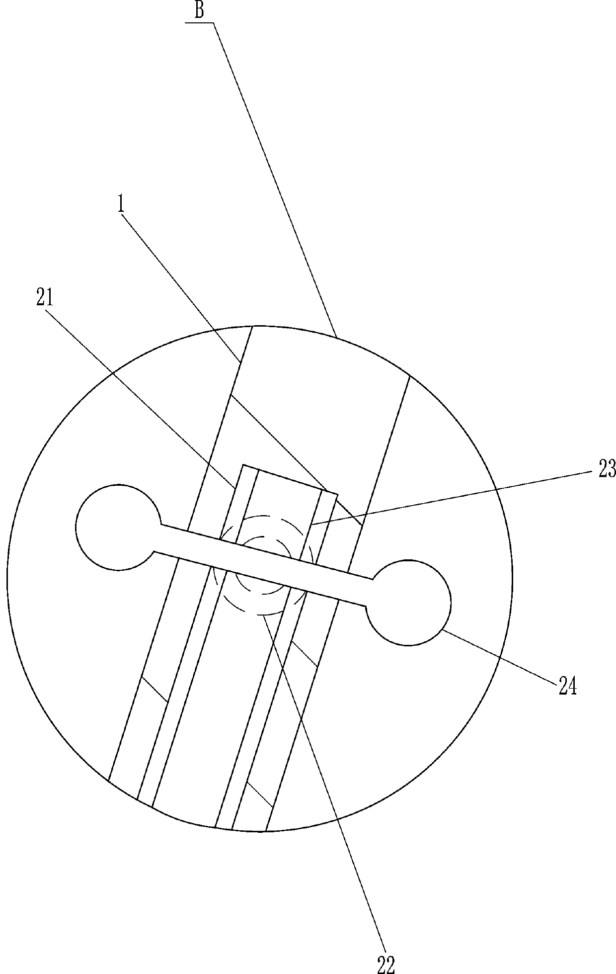
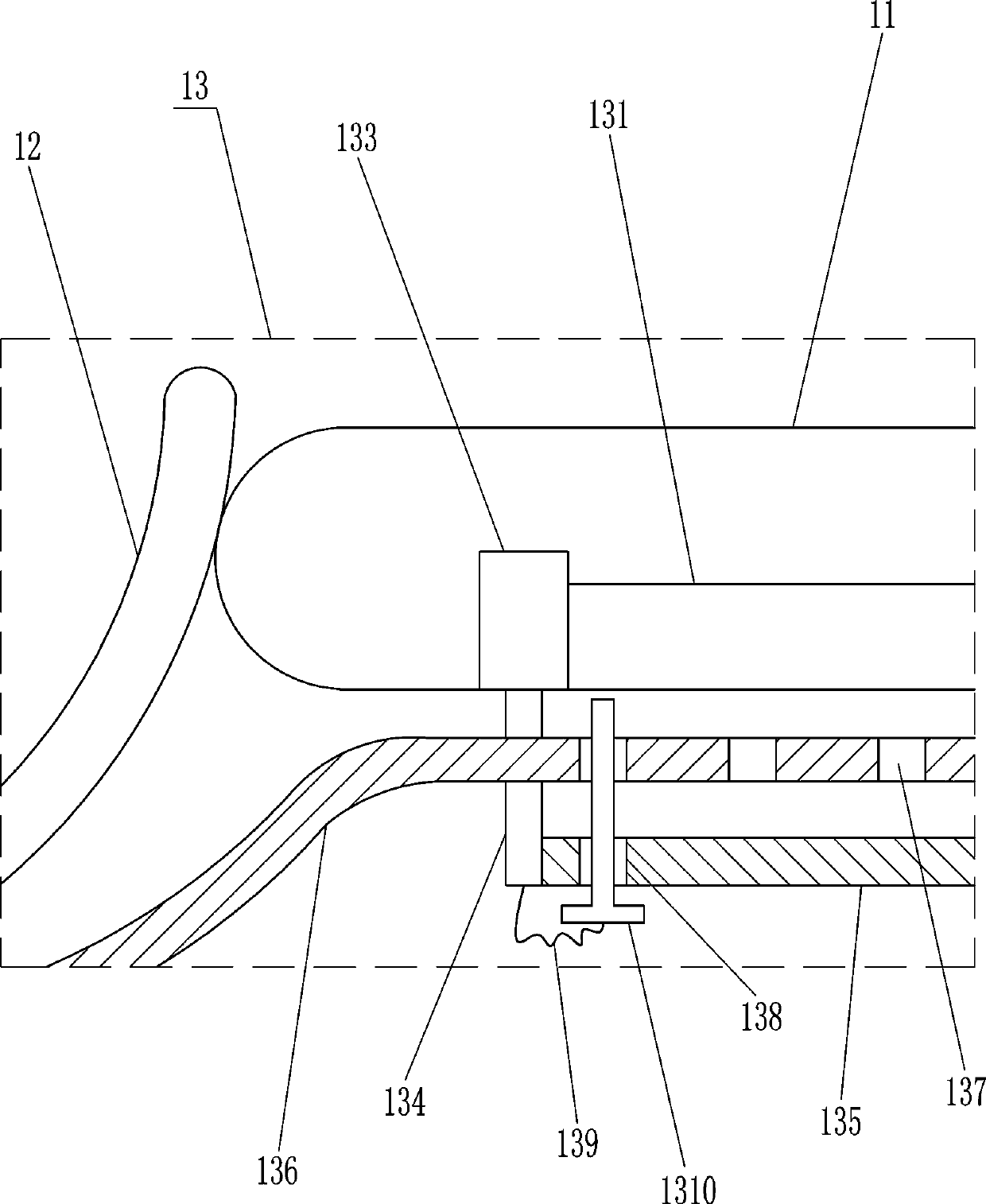
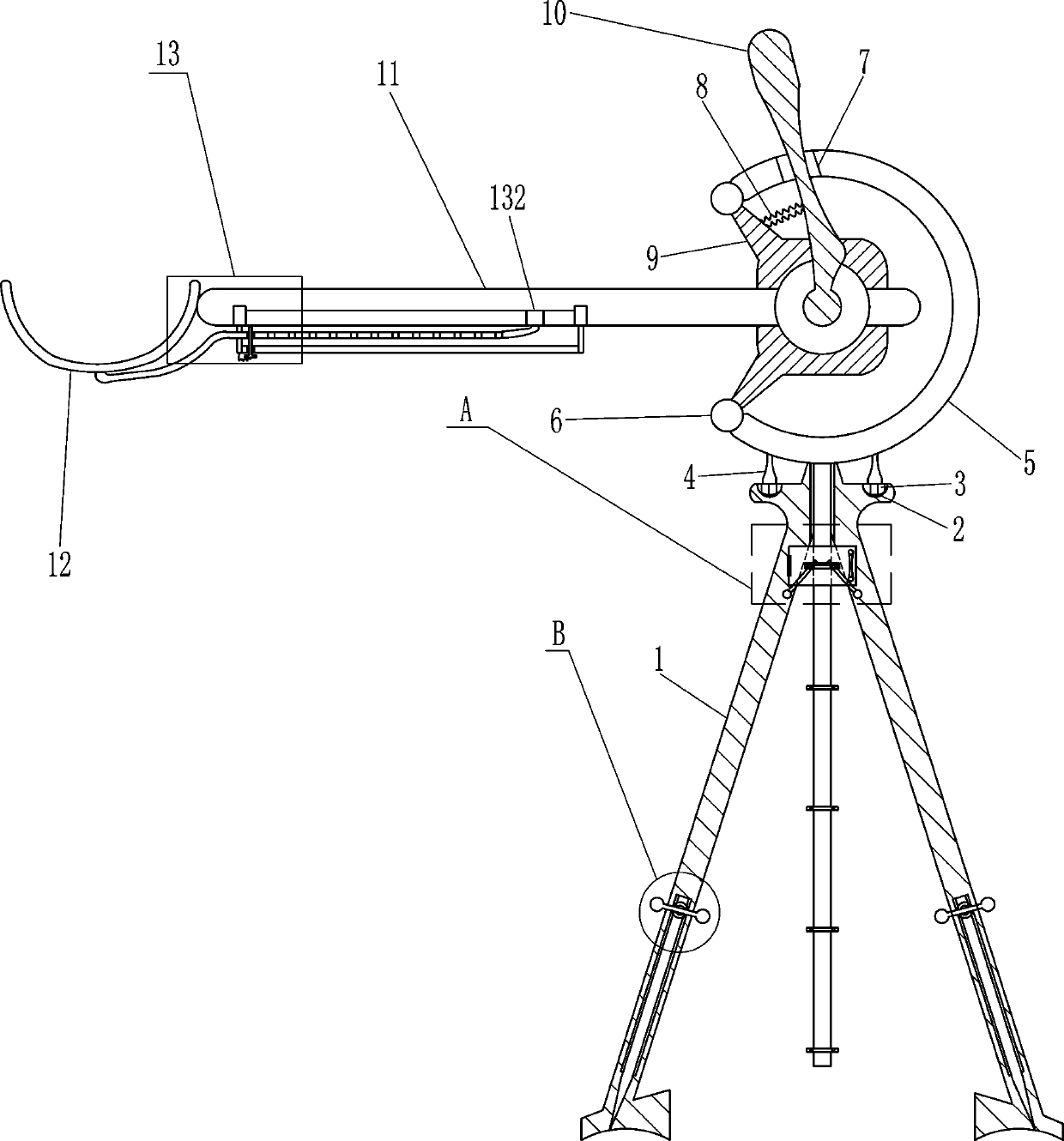
[0017] An aquaculture feeder such as Figure 1-2 As shown, it includes a mounting seat 1, a block 3, a connecting column 4, an arc-shaped slide rail 5, a circular stopper 6, a first slider 7, a first spring 8, a fixed block 9, a first rotating rod 10, Swing bar 11, U-shaped frame 12 and moving mechanism 13, the left and right sides of mounting base 1 top all have the draw-in groove 2 that plays a fixed role, and draw-in groove 2 is provided with block 3, and the top of block 3 is affixed with The connecting column 4 and the block 3 are connected to the connecting column 4 by welding, and the arc-shaped sliding rail 5 is installed between the tops of the left and right connecting columns 4, and the connecting column 4 is connected to the arc-shaped sliding rail 5 by means of bolt connection , both ends of the arc-shaped slide rail 5 are fixed with a circular block 6 that can prevent the first slider 7 from slipping out, and a fixed block 9 is fixed between the upper and lower c...

Embodiment 2

[0019] An aquaculture feeder such as Figure 1-2 As shown, it includes a mounting seat 1, a block 3, a connecting column 4, an arc-shaped slide rail 5, a circular stopper 6, a first slider 7, a first spring 8, a fixed block 9, a first rotating rod 10, Swing bar 11, U-shaped frame 12 and moving mechanism 13, the left and right sides of mounting base 1 top all have the draw-in groove 2 that plays a fixed role, and draw-in groove 2 is provided with block 3, and the top of block 3 is affixed with Connecting column 4, arc-shaped slide rail 5 is installed between the tops of the left and right two connecting columns 4, both ends of arc-shaped slide rail 5 are fixed with circular stoppers 6 that can prevent the first slide block 7 from slipping out, up and down A fixed block 9 is fixed between the two circular stoppers 6, and the front side of the fixed block 9 is rotatably connected with a swing rod 11, and the right part of the front side of the swing rod 11 is fixed with a first r...

Embodiment 3

[0022] An aquaculture feeder such as Figure 1-3 As shown, it includes a mounting seat 1, a block 3, a connecting column 4, an arc-shaped slide rail 5, a circular stopper 6, a first slider 7, a first spring 8, a fixed block 9, a first rotating rod 10, Swing bar 11, U-shaped frame 12 and moving mechanism 13, the left and right sides of mounting base 1 top all have the draw-in groove 2 that plays a fixed role, and draw-in groove 2 is provided with block 3, and the top of block 3 is affixed with Connecting column 4, arc-shaped slide rail 5 is installed between the tops of the left and right two connecting columns 4, both ends of arc-shaped slide rail 5 are fixed with circular stoppers 6 that can prevent the first slide block 7 from slipping out, up and down A fixed block 9 is fixed between the two circular stoppers 6, and the front side of the fixed block 9 is rotatably connected with a fork 11, and the right part of the front side of the fork 11 is fixed with a first rotating ro...


PUM


Abstract

The invention relates to a feeding device, in particular to a feeding device for aquaculture. The technical aim is to provide the feeding device for aquaculture which can lower labor intensity and prevent feed centralization. The feeding device for aquaculture comprises a mounting base, clamping blocks, connection columns, an arc slide rail, circular check blocks, a first slide block, first springs, a fixing block, a first rotation rod, a swing rod and the like; clamping grooves with a fixing function are formed in the left and right sides of the top of the mounting base, the clamping blocks are arranged in the clamping grooves, and the connection columns are fixedly connected to the tops of the clamping blocks; the arc slide rail is installed between the tops of the left and right connection columns. According to the feeding device for aquaculture, the position of a U-shaped frame can be adjusted through a mobile mechanism, in this way, a user can conveniently adjust the feeding distance of feed, and accordingly the situation can be avoided that since feeding of the feed is excessively centralized, scramble is caused.

Description

technical field [0001] The invention relates to a feeder, in particular to an aquaculture feeder. Background technique [0002] When feeding the fish in the pond, people need to put the feed in the pond. At present, when feeding the feed, people usually pour the feed into the container, and then people walk with the container and throw the feed by hand. In the pond, people’s labor intensity is relatively high, and the distance for people to throw feed is relatively short, and people throw feed more concentratedly, which will cause fish competition in the pond. In order to prevent fish competition in the pond People will dump the feed into the pond while walking with the container, and when the fish jumps the water, it will carry water, which will wet people's clothes. Contents of the invention [0003] In order to overcome the disadvantages that people throw the feed into the pond while walking with the container, the labor intensity of people is relatively high, and the ...

Claims


Application Information

Patent Timeline
Patent Type & Authority Applications(China)
IPC IPC(8): A01K61/80
CPCY02A40/81
Inventor 叶建德
Owner 叶建德
Why Eureka
Try Eureka