Display screen assembly base and multi-screen support
A technology for display screens and mounting seats, applied in the direction of machines/brackets, supporting machines, mechanical equipment, etc., can solve problems such as uneven gap spacing, inability to adjust the deflection angle of the display screen, and difficulty in solving practical use problems, etc., to achieve The upper and lower spacing are equal, the gap is uniform, and the effect of meeting the normal use requirements
- Summary
- Abstract
- Description
- Claims
- Application Information
AI Technical Summary
Problems solved by technology
Method used
Image
Examples
no. 1 example
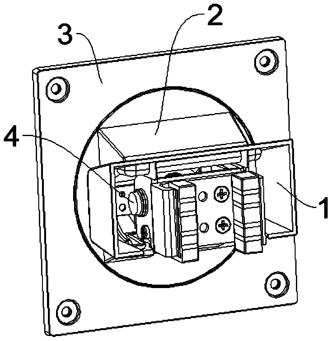
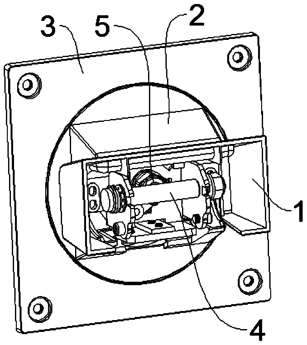
[0037] in, figure 1 A schematic diagram of the external structure of the mounting base of the display screen 6 provided for Embodiments 1 and 2 of the present invention; figure 2 It is a schematic diagram of the internal structure of the mounting base of the display screen 6 provided in Embodiments 1 and 2 of the present invention.
[0038] Please refer to figure 1 , figure 2 , the present embodiment provides a mounting seat for a display screen 6, which includes a base 1, a first movable part 2 and a second movable part 3; the base 1 is provided with a first rotating shaft 4, and the first movable part 2 passes through the first rotating shaft 4 is hinged to the base 1; the first movable part 2 is provided with a second rotating shaft 5, and the second movable part 3 is hinged to the first movable part 2 through the second rotating shaft 5; the first rotating shaft 4 and the second rotating shaft 5 are perpendicular to each other; The second movable part 3 is provided wi...
no. 2 example
[0042] in, figure 1 A schematic diagram of the external structure of the mounting base of the display screen 6 provided for Embodiments 1 and 2 of the present invention; figure 2 It is a schematic diagram of the internal structure of the mounting base of the display screen 6 provided in Embodiments 1 and 2 of the present invention.
[0043] Please refer to figure 1 , 2 , this embodiment provides a display screen 6 mounting base, which is roughly the same as the display screen 6 mounting base of the first embodiment, the difference between the two is that in the display screen 6 mounting base of this embodiment, the second movable part 3 and The second rotating shaft 5 is fixedly connected, and the rotation of the second rotating shaft 5 itself can drive the second movable part 3 to rotate.
[0044] In the above embodiments, the angle of the display screen 6 is adjusted by directly screwing the second rotating shaft 5 . Wherein, the second rotating shaft 5 can also be prov...
no. 3 example
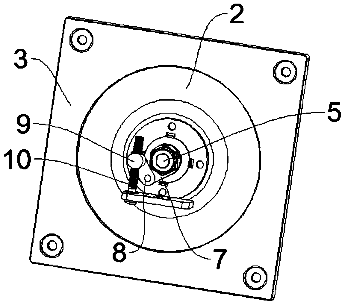
[0046] in, image 3 It is a schematic diagram of the internal structure of the mounting seat of the display screen 6 provided by Embodiment 3 of the present invention.
[0047] Please refer to image 3 , this embodiment provides a display screen 6 mounting base, which is roughly the same as the display screen 6 mounting base of the first embodiment, the difference between the two is that in the display screen 6 mounting base of this embodiment, the second movable part 3 and The second rotating shaft 5 is fixedly connected, and the rotation of the second rotating shaft 5 itself can drive the second movable part 3 to rotate.
[0048] Further, a fine adjustment device is also included, and the fine adjustment device is arranged between the second rotating shaft 5 and the first movable part 2 for adjusting the rotation angle of the second rotating shaft 5 .
[0049] Further, the fine-tuning device includes a first hinge rod 7, a second hinge rod 8, a screw joint 9 and an adjustm...
PUM
 Abstract
Description
Claims
Application Information
 - R&D
- Intellectual Property
- Life Sciences
- Materials
- Tech Scout
- Unparalleled Data Quality
- Higher Quality Content
- 60% Fewer Hallucinations
Browse by: Latest US Patents, China's latest patents, Technical Efficacy Thesaurus, Application Domain, Technology Topic, Popular Technical Reports.
© 2025 PatSnap. All rights reserved.Legal|Privacy policy|Modern Slavery Act Transparency Statement|Sitemap|About US| Contact US: help@patsnap.com


