Coal-fired boiler flue gas denitration catalyst separation apparatus
What is Al technical title?
Al technical title is built by PatSnap Al team. It summarizes the technical point description of the patent document.
A technology of denitration catalyst and separation device, which is applied in the field of coal-fired boiler flue gas denitration catalyst separation device, can solve the problems that the separation effect cannot meet the requirements, it is difficult to understand the reaction situation, and there is no alarm device, so as to prevent secondary pollution, The effect of increasing the service life and increasing the effect
Inactive Publication Date: 2019-06-21
周耀川
View PDF1 Cites 0 Cited by
Summary
Abstract
Description
Claims
Application Information
AI Technical Summary
This helps you quickly interpret patents by identifying the three key elements:
Problems solved by technology
Method used
Benefits of technology
Problems solved by technology
[0004] In view of the above problems, the present invention provides a coal-fired boiler flue gas denitrification catalyst separation device, which solves the problem of lack of anti-corrosion function, long-term replacement of parts, separation effect that cannot meet the requirements, lack of alarm device, and difficulty in understanding the internal response to the problem
Method used
Image
Click on the blue label to locate the original text in one second.
Reading with bidirectional positioning of images and text.
Examples
Embodiment 1
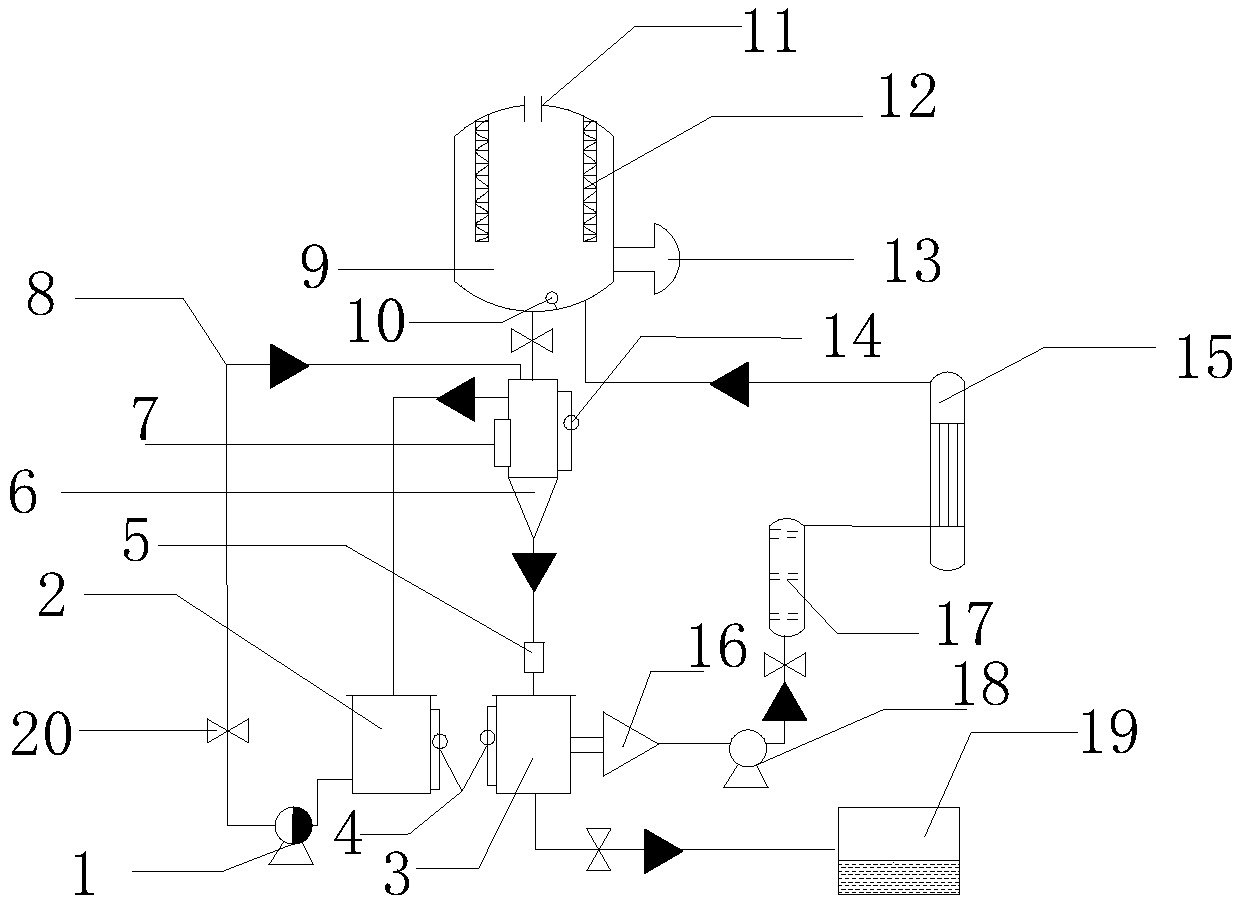
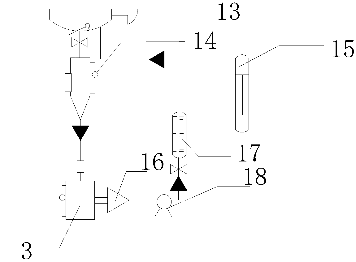
[0014] A coal-fired boiler flue gas denitrification catalyst separation device, the structure of which includes a clear liquid delivery pump 1, a clear liquid storage tank 2, a turbid liquid storage tank 3, a boundary gauge 2 4, a static mixer 5, a sedimentation separation tank 6, a liquid Ammonia injection port 7, anti-corrosion delivery pipeline 8, reaction kettle 9, high temperature resistant temperature detector 10, feed port 11, heating pipe 12, temperature alarm 13, boundary gauge 14, heat exchanger 15, two-way suspension Separator 16, membrane filter 17, turbid liquid delivery pump 18, sedimentation tank 19, control valve 20; described clear liquid delivery pump 1 is connected with clear liquid storage tank 2 through anti-corrosion delivery pipeline 8, and described clear liquid storage The tank 2 and the turbid liquid storage tank 3 are connected to the sedimentation separation tank 6, the sedimentation separation tank 6 is connected to the liquid ammonia injection port...
PUM
Abstract
The invention discloses a coal-fired boiler flue gas denitration catalyst separation apparatus. The structure of the coal-fired boiler flue gas denitration catalyst separation apparatus comprises a comprises a clear liquid conveying pump, a clear liquid storage groove, a turbid liquid storage groove, an interface position meter 2, a static mixer, a sedimentation separation groove, a liquid ammoniaspraying port, anticorrosion conveying pipelines, a reaction kettle, a high-temperature-resistant temperature detector, a material inlet, a heating pipe, a temperature alarm device, an interface position meter 1, a heat exchanger, a bidirectional suspension separator, a membrane filter, a turbid liquid conveying pump, a precipitation pool and control valves, wherein the clear liquid conveying pump is connected to the clear liquid storage groove through the anticorrosion conveying pipeline, the static mixer is connected to the turbid liquid storage groove through the anticorrosion conveying pipeline, the bidirectional suspension separator is connected to the turbid liquid storage groove through the anticorrosion conveying pipeline, the precipitation pool is connected to the turbid liquid storage groove through the anticorrosion conveying pipeline, and the heat exchanger is connected to the reaction kettle. According to the present invention, the coal-fired boiler flue gas denitration catalyst separation apparatus has anticorrosion function, can prolong the service life of the equipment, and can intuitively understand the internal reaction condition.
Description
technical field [0001] The invention relates to the technical field of chemical production, in particular to a coal-fired boiler flue gas denitrification catalyst separation device. Background technique [0002] In a chemical reaction, the catalyst must keep in good contact with the reaction medium, so mechanical stirring or air blowing stirring is generally used in the reactor to promote the continuous renewal of the surface of the catalyst particles and the surface of the reactants, and the catalyst particles are in a suspended flow state in the reactor . The whole process is continuous production. After the reactants are converted into products, they are discharged from the reactor, and then the catalyst particles are also taken out of the reactor along with the products. In order to recycle the catalyst, solid-liquid separation must be carried out. Filtration and pressure filtration are generally used. During filtration, with the formation of filter cake, the resistance...
Claims
Application Information
Patent Timeline
Application Date:The date an application was filed.
Publication Date:The date a patent or application was officially published.
First Publication Date:The earliest publication date of a patent with the same application number.
Issue Date:Publication date of the patent grant document.
PCT Entry Date:The Entry date of PCT National Phase.
Estimated Expiry Date:The statutory expiry date of a patent right according to the Patent Law, and it is the longest term of protection that the patent right can achieve without the termination of the patent right due to other reasons(Term extension factor has been taken into account ).
Invalid Date:Actual expiry date is based on effective date or publication date of legal transaction data of invalid patent.