AI technical title is built by Patsnap AI team. It summarizes the technical point description of the patent document.
A cleaning device and mold technology, applied in water/sewage treatment, water/sludge/sewage treatment, filtration treatment, etc., can solve problems such as damage to the inner surface of the mold, improve cleaning quality, save time and labor costs, and structure simple effect
Active Publication Date: 2018-12-07
GREE ELECTRIC APPLIANCES ZHENGZHOU +1
View PDF1 Cites 5 Cited by
Summary
Abstract
Description
Claims
Application Information
AI Technical Summary
This helps you quickly interpret patents by identifying the three key elements:
Problems solved by technology
Method used
Benefits of technology
Problems solved by technology
[0006] Therefore, the technical problem to be solved by the present invention is to overcome the defect that the injection mold waterway automatic cleaning device in the prior art will damage the inner surface of the mold during the cleaning process, thereby providing a method that will not damage the inner surface of the mold during the cleaning process. Carry out damaged mold waterway cleaning device
Method used
Image
Click on the blue label to locate the original text in one second.
Reading with bidirectional positioning of images and text.
Examples
Embodiment 1
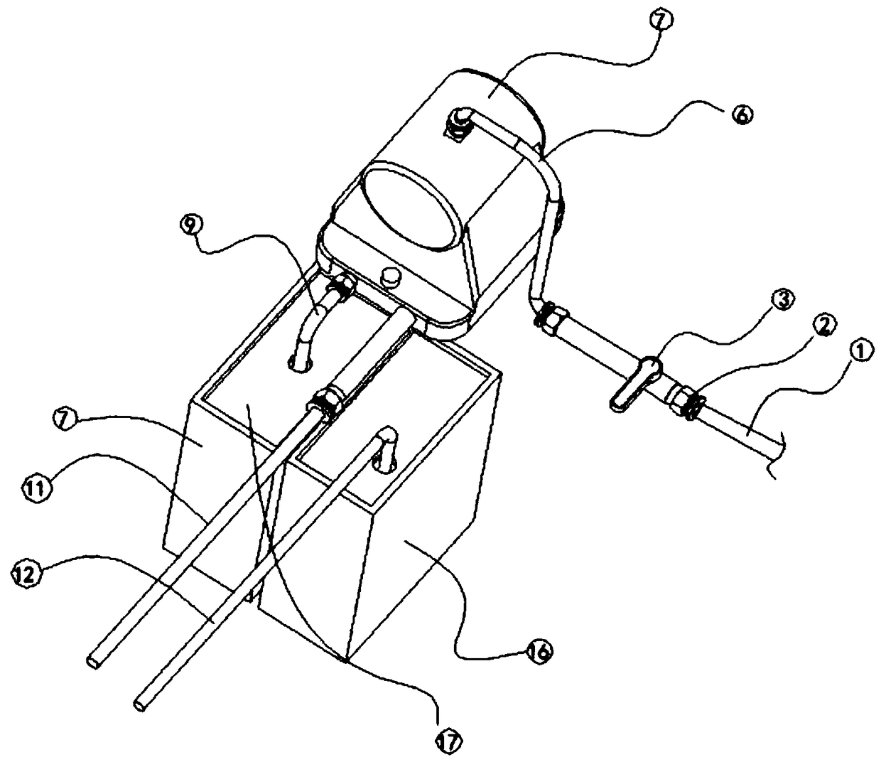
[0049] like figure 1 Shown, a kind of mold waterway cleaning device of the present invention comprises:
[0050] The liquid storage tank 17 is used to store the cleaning liquid;
[0051] The liquid return tank 16 is used to recover the cleaning liquid;
[0052] pump assemblies, including pumps;
[0053] The first liquid inlet pipe 9, its first end communicates with the liquid storage tank 17, and its second end communicates with the liquid inlet port of the pump;
[0054] The second liquid inlet pipe 11, its first end communicates with the liquid outlet of the pump, and the second end is suitable for connecting with the mold water inlet pipe joint;
[0055] The first end of the liquid return pipe 12 is suitable for connecting with the mold outlet pipe joint, and the second end is suitable for communicating with the liquid return tank 16 .
[0056]By arranging the liquid storage tank 17 and the liquid return tank 16, it is possible to prevent the cleaned cleaning liquid fro...
Embodiment 2
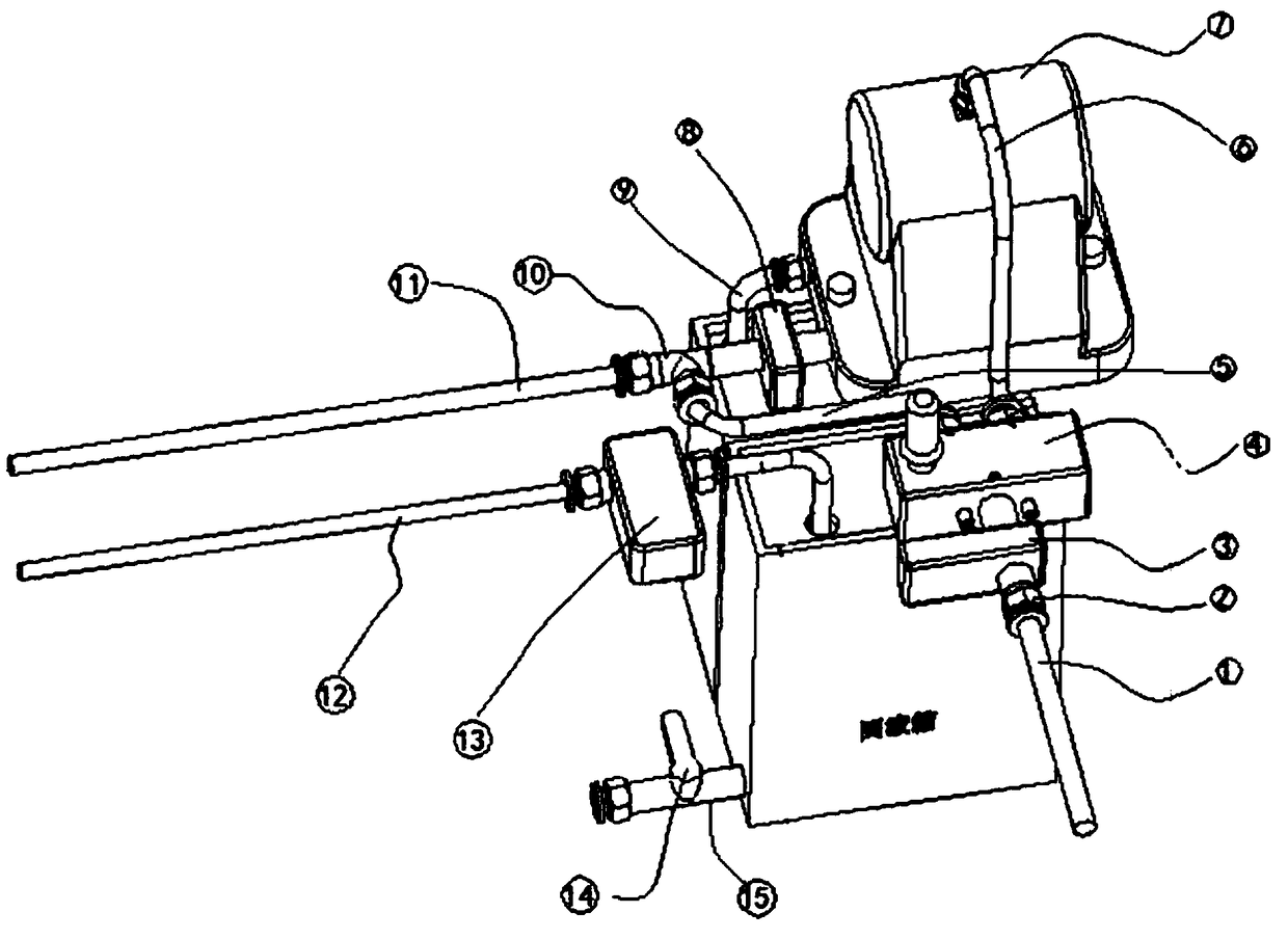
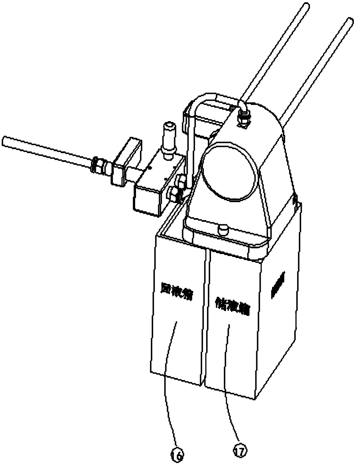
[0066] like Figure 2-4 As shown, on the basis of Embodiment 1, this implementation 2 also includes a blowing pipeline structure, and the blowing pipeline structure includes
[0067] A three-way joint 10 is arranged on the second liquid inlet pipe 11;
[0068] The liquid outlet valve 8 is arranged on the second liquid inlet pipe 11 and is located between the three-way joint 10 and the air-controlled pump;
[0069] An air supply pipeline assembly, one end communicates with the tee joint 10, and the other end communicates with the compressed air source;
[0070] When cleaning the mold, control the air supply pipeline assembly to cut off the air supply to the second liquid inlet pipe 11, and control the opening of the inlet valve 3 and the opening of the liquid outlet valve 8;
[0071] When drying the mold, control the liquid outlet valve 8 to close, and control the air supply pipeline assembly to communicate with the second liquid inlet pipe 11 to supply air.
[0072] Due to ...
PUM
Abstract
The invention relates to a die water path cleaning device. The die water path cleaning device comprises a liquid storage box used for storing cleaning liquid, a liquid return box used for recycling the cleaning liquid, a pump assembly comprising a pump, a first liquid inlet pipe, a second liquid inlet pipe and a liquid return pipe, wherein the first end of the first liquid inlet pipe communicateswith the liquid storage box, the second end of the first liquid inlet pipe communicates with a liquid inlet of the pump, the first end of the second liquid inlet pipe communicates with a liquid outletof the pump, and the second end of the second liquid inlet pipe is suitable for being connected with a die water inlet pipe connector. The first end of the liquid return pipe is suitable for being connected with a die water outlet pipe connector, and the second end of the liquid return pipe is suitable for communicating with the liquid return box. The die water path cleaning device has the beneficial effects of being resistant to corrosion, high in cleaning efficiency, short in cleaning time and suitable for various kinds of cleaning liquid.
Description
technical field [0001] The invention relates to the field of molds, in particular to a mold waterway cleaning device. Background technique [0002] Injection mold is the most important molding equipment in the processing of injection molded products. The life of the mold directly affects the cost and quality of the product. Improving the quality of injection molds, doing a good job of mold maintenance and maintenance, and prolonging the service life of molds have always been important topics for injection molding factories to reduce costs. [0003] In terms of mold maintenance and maintenance, in addition to the wear and tear of parts, the cooling failure of the mold waterway has always been an important problem that affects the life of the mold, product quality and mold production efficiency. Therefore, the maintenance and cleaning of the mold waterway is very important for the production of injection molds and products. [0004] Chinese patent document CN20346027U disclo...
Claims
Application Information
Patent Timeline
Application Date:The date an application was filed.
Publication Date:The date a patent or application was officially published.
First Publication Date:The earliest publication date of a patent with the same application number.
Issue Date:Publication date of the patent grant document.
PCT Entry Date:The Entry date of PCT National Phase.
Estimated Expiry Date:The statutory expiry date of a patent right according to the Patent Law, and it is the longest term of protection that the patent right can achieve without the termination of the patent right due to other reasons(Term extension factor has been taken into account ).
Invalid Date:Actual expiry date is based on effective date or publication date of legal transaction data of invalid patent.

