Centrifugal fan provided with centrifugal force separation device

A centrifugal fan and separation device technology, which is applied to the components of the pumping device for elastic fluids, mechanical equipment, non-variable-capacity pumps, etc. Oil fume gas, air purification and other issues, to achieve the effect of improving the separation efficiency and quality and optimizing the circumference

Active Publication Date: 2019-06-21
关云龙
View PDF7 Cites 1 Cited by
  • Summary
  • Abstract
  • Description
  • Claims
  • Application Information

AI Technical Summary

Problems solved by technology

But the problem that is easy to occur is: due to the large distance between the volute tongue at the outlet end of the centrifugal fan and the upper end of the separation box, part of the air sucked by the wind wheel flows back to the fan casing, while most of it is discharged, and the fan Part of the air in the shell is discharged out of control, and it is in a state where it cannot completely separate and process oil fume gas and air purification, resulting in a decrease in separation efficiency. When the separation efficiency is constant, the content of particulate matter is less and it is easier to meet the standard, and the content of particulate

Method used


Image

  • Centrifugal fan provided with centrifugal force separation device
  • Centrifugal fan provided with centrifugal force separation device
  • Centrifugal fan provided with centrifugal force separation device

Examples


Embodiment 2

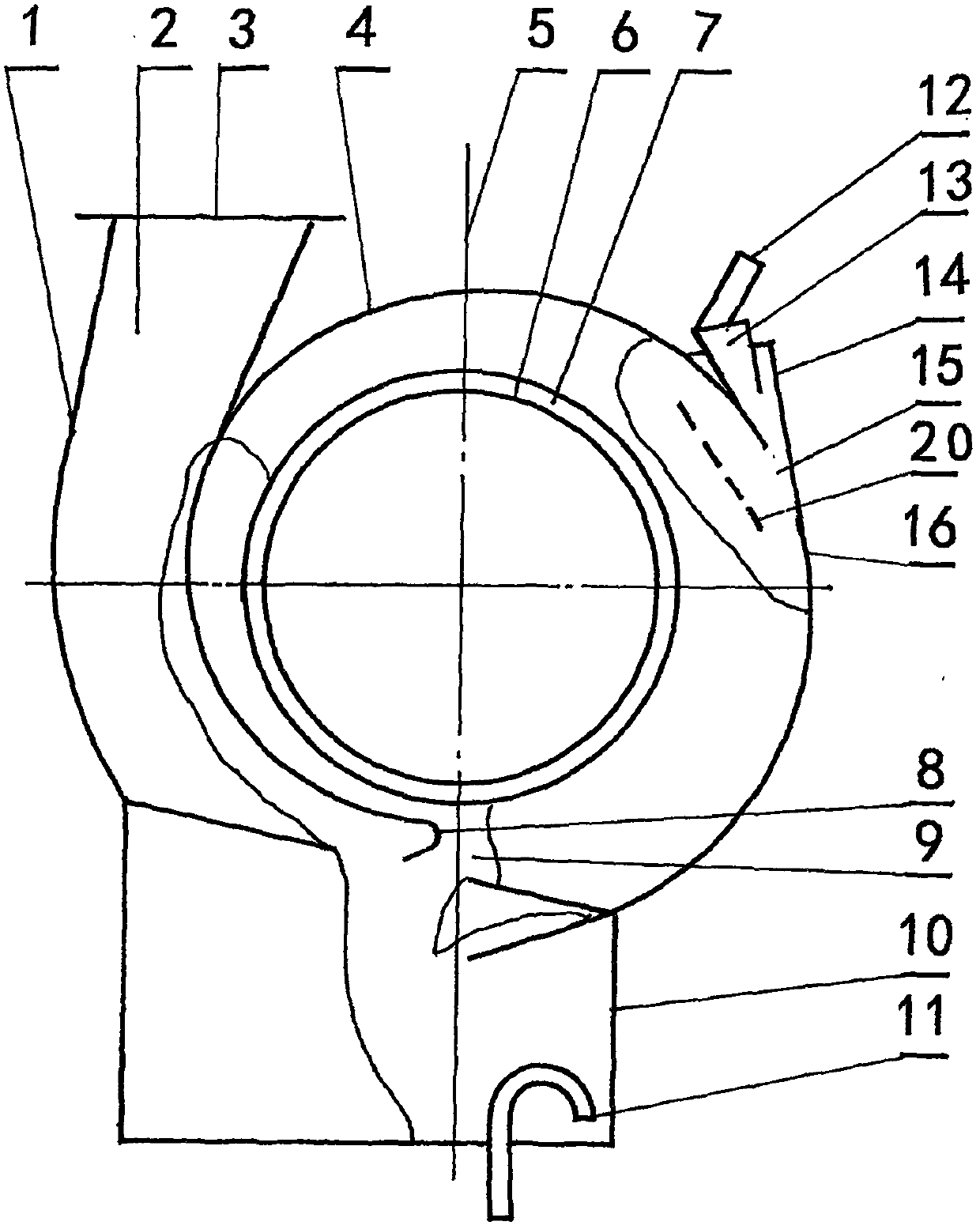
[0034] Such as figure 2 Shown, the centrifugal blower fan that installs the centrifugal force separation device in the present embodiment is on the basis of embodiment 1, wherein: it also includes by annular separation plate 4, angle groove body 14, water film spray nozzle 13. The water film spray nozzle device formed by the water film spray nozzle outlet 15 and the water inlet pipe 12 is formed by overlapping the ends of the annular separation plate 4 and the annular separation plate 16 on the side of the fan housing 1 and the center line 5. There is a corner-shaped tank 14 with an opening, and the water film spray nozzle 13 is placed in the opening of the angle-shaped tank 14. There is a gap between the outlet 15 of the water film spray nozzle and the inner wall of the annular separation plate 16, and the water inlet pipe 12 is located in the ring On the outside of the separation plate 16, the length of the angled groove body 14 is consistent with the thickness of the fan h...

Embodiment 3

[0036] Such as figure 2 As shown in the dotted line, the centrifugal fan equipped with centrifugal force separation device in this embodiment is based on the embodiment 2 with an added wind deflector 20, wherein: it also includes an annular separation plate 4 on one side of the central line 5 The water film spray nozzle 13 outlet position that the upper end is provided with is provided with deflector 20, and the upper end of deflector 20 is provided with annular separating plate 4 inwalls, and water film spray nozzle 13 is provided with gap, and the length of deflector 20 is the same as that of blower casing. Body 1 has the same thickness.

Embodiment 4

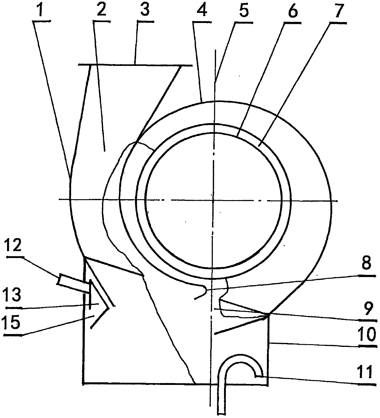
[0038] Such as image 3 As shown, the centrifugal blower equipped with the centrifugal force separation device in the present embodiment is based on the embodiment 1 and it also includes a water film spray nozzle 13 installed on the inner wall of the separation box 10 body and the fan outlet 9. On one side, a gap is provided between the water film nozzle outlet 15 and the inner wall of the separation box 10, and the water inlet pipe 12 is located at the outer end of the separation box 10.


PUM


Abstract

The invention relates to a centrifugal fan for separating oil smoke, purifying air and dirt. The centrifugal fan is to mainly solve the problem that an existing centrifugal fan is not provided with aseparation device under the action of centrifugal force, or the technical difficulty of poor separation efficiency of the separation device. According to the technical scheme, the centrifugal fan comprises a fan shell, an impeller and a separation device, wherein the separation device is composed of an annular separation plate, an induced draft guide pipe, a separation box body and a blowdown water seal pipe; the annular separation plate is an annular body with opening formed in two opposite ends; the openings of the annular body are formed in a manner that a fan outlet is inverted at the inner upper end of the separation box body; one end of the annular separation plate is combined with the upper end of one side of the separation box body; the other end of the annular separation plate isarranged at the upper end of the separation box body and is provided with a spiral tongue; an induced draft pipe is combined with the outer side of the annular separation plate and the upper end of the other side of the separation box body is provided with an induced draft pipe outlet; the bottom of the separation box is provided with a pollution discharge water seal pipe; the width of the annularseparation plate is consistent with the thickness of the fan shell; and a fan inlet and a wind wheel are arranged in the middle of the annular separating plate

Description

technical field [0001] The invention relates to a centrifugal fan for separating oil fume, purifying air and separating dust and dirt. Background technique [0002] In the prior art, devices such as filter screens, cloth bags, and electrostatic precipitators with separation functions are installed on the outer end of the centrifugal fan to remove dust and separate particles in the oil fume gas. The above methods can be summarized as mesh filtration technology. This technical method When the gas containing particulate matter passes through the grid, the particulate matter can also pass through at the same time, resulting in leakage; when this technical method is used, the grid will be blocked so that it cannot be used; at the same time, this technical method cannot achieve fine separation. The finer the grid, the easier it is to block. Aiming at the above-mentioned technical difficulties, the patented technology ZL201621072230.X No. Centrifugal fan equipped with separation o...

Claims


Application Information

Patent Timeline
IPC IPC(8): F04D17/08F04D29/70F04D29/66
Inventor 关云龙
Owner 关云龙
Why Eureka
Try Eureka