Electrical connector and manufacturing method thereof

A technology of an electrical connector and a manufacturing method, which is applied in the direction of connection, fixed connection, and parts of the connection device, etc., can solve the problems of wasting time, rising cost, and low work efficiency.

Active Publication Date: 2019-06-21
DEYI PRECISION ELECTRONIC IND CO LTD PANYU
View PDF5 Cites 1 Cited by
  • Summary
  • Abstract
  • Description
  • Claims
  • Application Information

AI Technical Summary

Problems solved by technology

[0005] The defect of the prior art is that multiple supports of the electrical connector are assem

Method used


Image

  • Electrical connector and manufacturing method thereof
  • Electrical connector and manufacturing method thereof
  • Electrical connector and manufacturing method thereof

Examples


Embodiment Construction

[0054] In order to facilitate a better understanding of the purpose, structure, features, and effects of the present invention, the present invention will now be further described in conjunction with the accompanying drawings and specific embodiments.

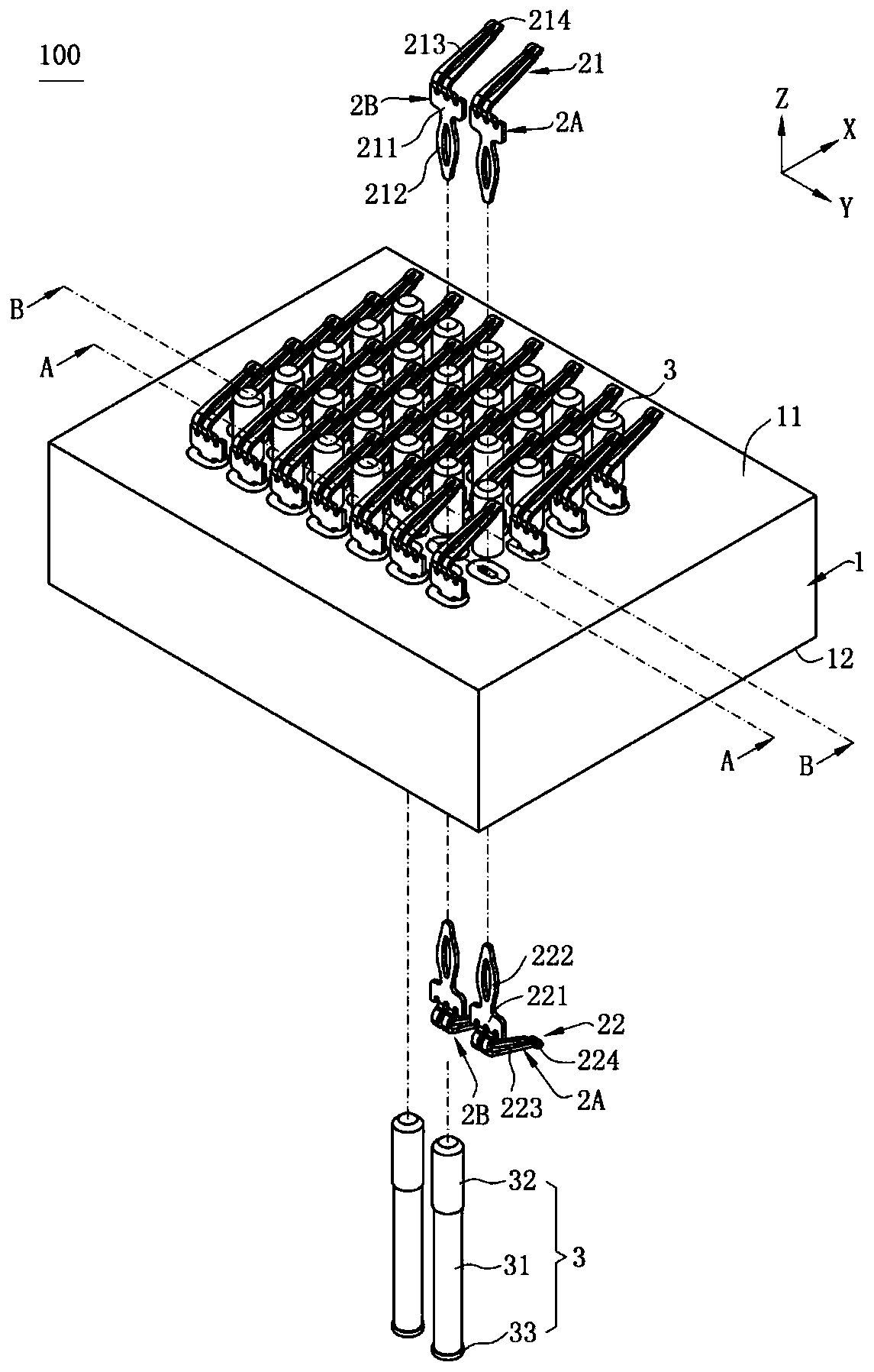
[0055] Such as figure 1 Shown is the first embodiment of the electrical connector 100 of the present invention. The electrical connector 100 defines an up-down direction Z, a front-back direction X and a left-right direction Y perpendicular to the up-down direction Z and perpendicular to each other.

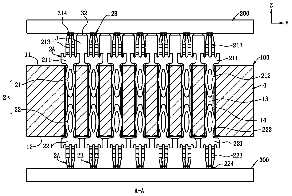
[0056] Such as figure 1 with figure 2 As shown, the electrical connector 100 is used to connect a first docking element 200 and a second docking element 300, which mainly includes a substrate 1 and a plurality of conductive terminals 2 arranged on the substrate 1 and a plurality of the The support member 3, in this embodiment, the first docking element 100 is a chip module, the substrate 1 is a circuit board, and the second doc...


PUM


Abstract

The invention discloses a manufacturing method of an electrical connector. The manufacturing method comprises the following steps of: S1, providing a substrate, wherein the substrate is provided witha plurality of conductive parts and a plurality of through holes, and the through holes penetrate through the substrate up and down; S2, placing the substrate in a mold, injecting liquid plastic intothe mold, enabling the liquid plastic to flow into the plurality of through holes, and forming a connector and a plurality of supporting members integrally connected by the connector after the liquidplastic is cooled, wherein the supporting members are contained in the corresponding through holes and upwardly protrude out of the substrate, and the connector is located below the substrate; S3, taking the substrate, the plurality of supporting members and the connector out from the mold; and S4, forming a plurality of first terminals, wherein each of the first terminals is provided with a firstconduction part and a first contact part for upwardly conducting the first conduction part, the plurality of first guiding parts are downwardly and correspondingly conducted to a plurality of conductive parts, so that the electric connector is obtained. The supporting members are integrally formed on the substrate, so that the implantation time is saved, the cost is low and the working efficiencyis improved.

Description

[0001] 【Technical field】 [0002] The invention relates to an electrical connector and a manufacturing method thereof, in particular to an electrical connector in which a plurality of supporting parts are integrally formed and a manufacturing method thereof. [0003] 【Background technique】 [0004] The electrical connector used to connect the chip module includes a substrate and a plurality of conductive terminals fixed on the substrate. One end of the conductive terminal is welded on the circuit board through solder balls, and the other end is in contact with the conductor of the chip module, thereby To realize the electrical conduction between the chip module and the circuit board, a plurality of through holes are provided in the middle of the substrate, and a plurality of support members are correspondingly assembled in the plurality of through holes one by one to support the chip module. [0005] The disadvantage of the prior art is that the plurality of supporting members ...

Claims


Application Information

Patent Timeline
IPC IPC(8): H01R13/405H01R13/627H01R13/629H01R43/24
CPCB29C45/14311B29C45/14467B29C2045/14327H01R12/714H01R12/91H01R13/2442H01R43/20H01R12/57H01R12/58H01R12/7076H01R12/716H01R13/24H01R13/504
Inventor 陈裕昇彭治国
Owner DEYI PRECISION ELECTRONIC IND CO LTD PANYU
Why Eureka
Try Eureka