A method and device used in a wireless communication terminal and a base station
A wireless communication and wireless signal technology, applied in the field of terminals, base stations and devices used for wireless communication, can solve the problem of increasing the number of blind detections, and achieve the effect of reducing the complexity of blind detection
- Summary
- Abstract
- Description
- Claims
- Application Information
AI Technical Summary
Problems solved by technology
Method used
Image
Examples
Embodiment 1
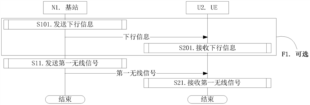
[0199] Embodiment 1 illustrates the flow chart of wireless transmission, as attached figure 1 shown. attached figure 1 In , the base station N1 is the serving cell maintenance base station of the UE U2. attached figure 1 , the steps in box F1 are optional.
[0200] For N1, send downlink information in step S101; send the first wireless signal in step S11.
[0201] For U2, receive downlink information in step S201; receive a first wireless signal in step S21.
[0202] In Embodiment 1, the bits in the first bit block are used by the N1 for the input of the channel coding in this application. Part or all of the symbols in the first symbol block are used by the N1 to generate the first wireless signal, and the first symbol block is generated by performing modulation mapping on the output of the channel coding. The number of bits in the first bit block is Z, where Z is one of K candidate values, the candidate value is a positive integer, and K is a positive integer greater th...
Embodiment 2
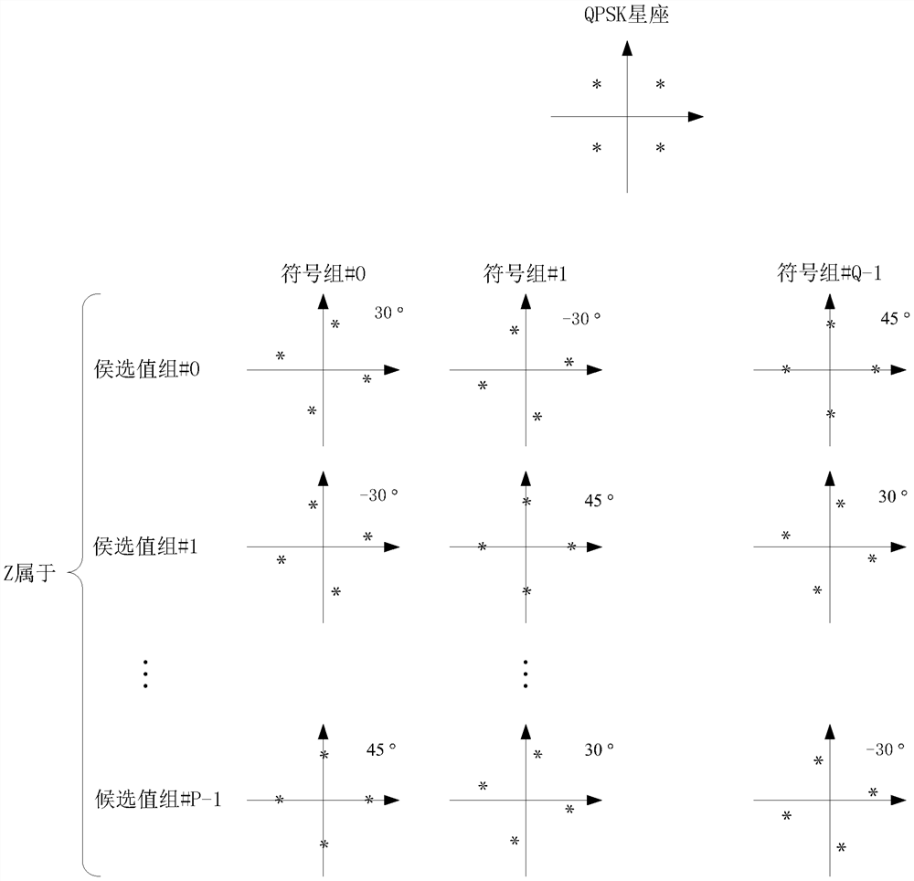
[0289]Embodiment 2 illustrates a schematic diagram of the relationship between the number of bits in the first bit block and the constellation pattern corresponding to the symbols in the first symbol block, as shown in the attached figure 2 shown.
[0290] In Embodiment 2, the first symbol block includes Q symbol groups, the Q is a positive integer greater than 1, and the constellation patterns corresponding to the symbols in each symbol group are the same, and the Q symbol groups The constellation patterns corresponding to any two different symbol groups in the symbol group are different, and the symbol group includes a positive integer number of symbols. The number of bits in the first bit block is Z, where Z is one of K candidate values, the candidate value is a positive integer, and K is a positive integer greater than 1. The K candidate values are divided into P candidate value groups, each of the candidate value groups includes a positive integer number of the candid...
Embodiment 3
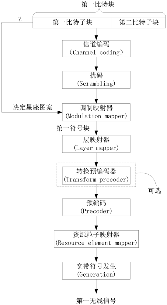
[0311] Embodiment 3 illustrates a schematic diagram of the relationship between the first bit block and the first wireless signal, as shown in the attached image 3 shown.
[0312] In Embodiment 3, the bits in the first bit block are used for the input of the channel coding in this application. Some or all symbols in a first symbol block are used to generate the first radio signal, and the first symbol block is generated by performing modulation mapping on the output of the channel coding. The number of bits in the first bit block is Z, where Z is one of K candidate values, the candidate value is a positive integer, and K is a positive integer greater than 1. The constellation pattern corresponding to at least one symbol in the first symbol block is related to the Z. Any two of the candidate values among the K candidate values are not equal. The first block of symbols includes a positive integer number of symbols. The first bit block includes a first bit sub-block and ...
PUM
 Abstract
Description
Claims
Application Information
 - R&D
- Intellectual Property
- Life Sciences
- Materials
- Tech Scout
- Unparalleled Data Quality
- Higher Quality Content
- 60% Fewer Hallucinations
Browse by: Latest US Patents, China's latest patents, Technical Efficacy Thesaurus, Application Domain, Technology Topic, Popular Technical Reports.
© 2025 PatSnap. All rights reserved.Legal|Privacy policy|Modern Slavery Act Transparency Statement|Sitemap|About US| Contact US: help@patsnap.com


