
Stationary orbit real aperture microwave detecting satellite configuration

A geostationary orbit and microwave detection technology, applied in the overall field of satellites, can solve the problem that it cannot well adapt to the mechanical environment and high-precision installation requirements of the launch main section, cannot make full use of the carrier fairing, and cannot realize the main reflector and the microwave detector. The problems such as high-precision expansion of the sub-reflector can achieve the effects of releasing the connection stress, reducing the deformation on the rail, and achieving high profile and position accuracy.

Active Publication Date: 2019-06-25
SHANGHAI SATELLITE ENG INST
View PDF7 Cites 2 Cited by
  • Summary
  • Abstract
  • Description
  • Claims
  • Application Information

AI Technical Summary

Problems solved by technology

However, this invention cannot make full use of the space resources in the launch fairing, nor can it well adapt to the mechanical environment and high-precision installation requirements of the active launch section, and it cannot realize the high-precision deployment of the main reflector and the sub-reflector of the microwave detector.

Method used


Image

  • Stationary orbit real aperture microwave detecting satellite configuration

Examples


Embodiment

[0031] Before describing in conjunction with specific embodiments, the coordinate systems involved are described as follows:

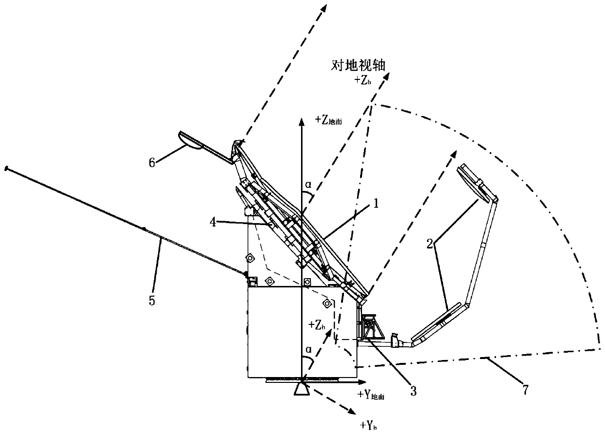
[0032] Satellite body coordinate system: coordinate origin O b is the center of mass of the satellite, +X b The axis points to the direction of satellite flight, +Z b The axis points to the sub-satellite point, +Y b Axis and +Z b 、+X b The axes form a right-handed Cartesian coordinate system;

[0033] Satellite ground coordinate system: coordinate origin O 地面 is the geometric center of the star-arrow separation surface, +Z 地面 Axis vertical star arrow separation face up, +Y 地面 Axis facing away from satellite solar wing, +X 地面 Axis and +Y 地面 、+Z 地面 The axes form a right-handed Cartesian coordinate system.

[0034] refer to figure 1 , the configuration of the geostationary orbit real-aperture microwave detection satellite related to the present invention, the configuration includes: the main reflector 1 of the geostationary orbit real-aperture...


PUM


Abstract

The invention relates to a stationary orbit real aperture microwave detecting satellite configuration in the overall technical field of satellites. The stationary orbit real aperture microwave detecting satellite configuration comprises a satellite platform, a microwave detector, a microwave detector quasi-optical system, a locking / release device, a solar wing, a digital transmission antenna, anda light blocking device, wherein a main reflection surface and a secondary reflection surface of the microwave detector are pressed on the satellite platform, and the main reflection surface and the secondary reflection surface are unlocked and deployed in place after the satellite and a launcher are separated; the microwave detector quasi-optical system is installed and embedded in the satelliteplatform by a micro-deformation frame; the solar wing is mounted on a cooling surface of the satellite platform; the digital transmission antenna is mounted on the top of the satellite platform through a bracket; the satellite platform and the microwave detector are inclined, that is, a certain angle exists between a ground observation axis and a satellite Z axis (that is, +Z ground); and after the orbit is fixed, over-constrained connection between the microwave detector and the satellite platform is unlocked, and the light blocking mechanism is deployed. The stationary orbit real aperture microwave detecting satellite configuration fully utilizes space resources in a fairing, and adapts to a mechanical environment of an active segment and high-precision installation requirements, so thathigh-precision deployment of the main reflection surface and the secondary reflection surface of the microwave detector is achieved.

Description

technical field [0001] The invention relates to the general technical field of satellites, in particular to a configuration of a geostationary orbit real-aperture microwave detection satellite. Background technique [0002] At present, geostationary orbit remote sensing satellites are mainly optical remote sensing satellites represented by Fengyun-4 and Gaofen-4. The observation spectrum ranges from visible light to infrared bands. The size of remote sensing instruments is generally smaller than or equivalent to satellite platforms. This type of remote sensing instrument is directly installed on the ground (that is, the earth observation axis is parallel to the Z-axis of the satellite), and the interface with the satellite platform is clear (usually several installation points are set on a plane), and they are generally thermally isolated , and there is no need to unfold the remote sensor. There are no strict requirements on the deployment sequence of the installed solar wi...

Claims


Application Information

Patent Timeline
Patent Type & Authority Applications(China)
IPC IPC(8): B64G1/10B64G1/22B64G1/64B64G1/44
Inventor 周徐斌陈晓杰董瑶海朱振华王萌潘高伟陶炯鸣王皓许娜
Owner SHANGHAI SATELLITE ENG INST
Learn More