Variable volume meter body

A meter and variable volume technology, applied in the direction of volume measurement, measurement capacity, volume/mass flow generated by mechanical effects, etc., can solve the problems of inaccurate measurement, small driving force, non-measurement, etc., and achieve reduced pressure loss and reliable The effect of folding and high measurement accuracy

Inactive Publication Date: 2008-04-23
陈冠一
View PDF5 Cites 0 Cited by
  • Summary
  • Abstract
  • Description
  • Claims
  • Application Information

AI Technical Summary

Problems solved by technology

If the flow rate is less than a certain set value, although the fluid still flows through the blades, due to the small driving force, the measurement will be inaccurate or even not measured.

Method used


Image

  • Variable volume meter body
  • Variable volume meter body
  • Variable volume meter body

Examples


Embodiment 1

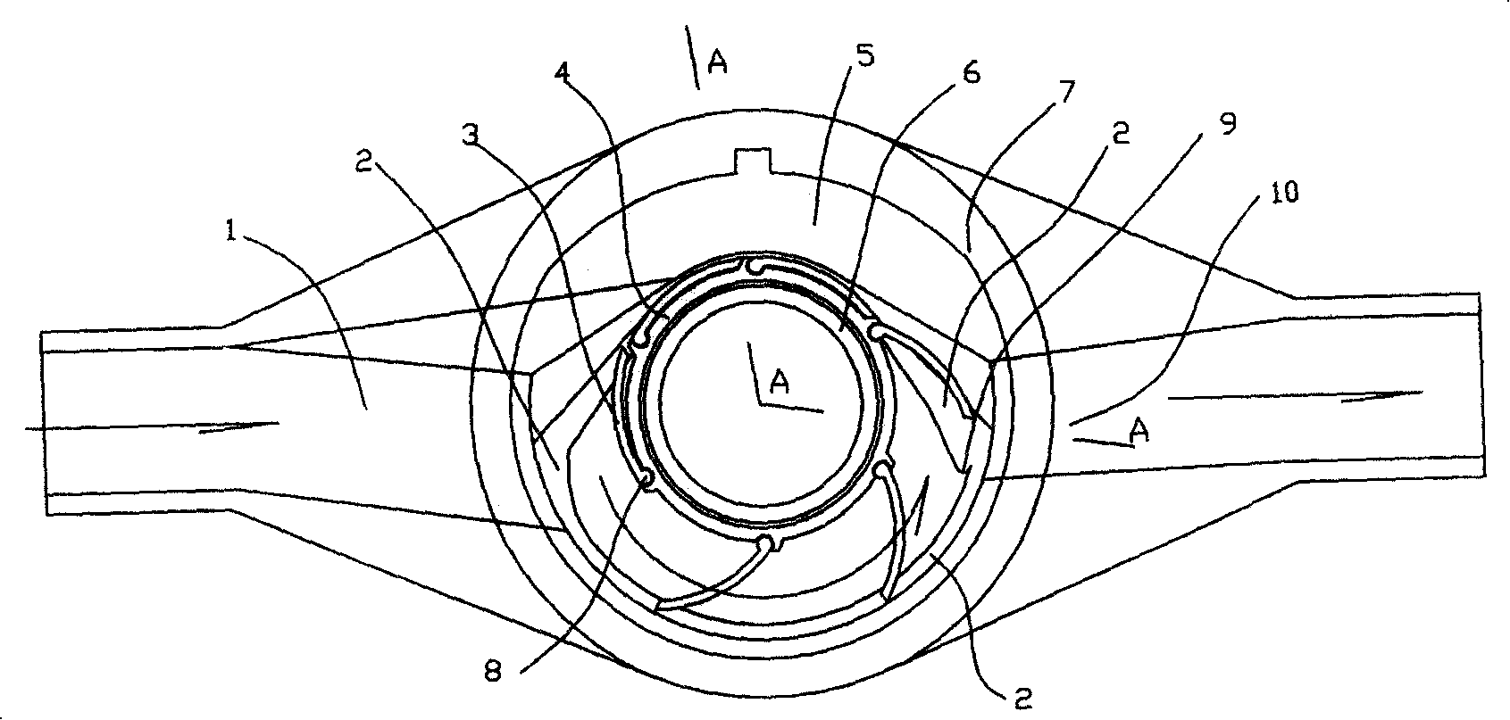
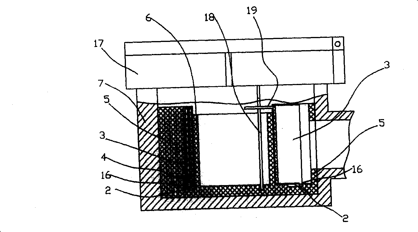
[0023] Such as figure 1 , 2 As shown, the meter body of this kind of variable volume meter has an inner cavity bushing 5 made of non-toxic wear-resistant plastic embedded in the meter body shell 7, and the inner cavity of the bushing 5 constitutes the inner cavity of the meter. An impeller device is installed in the middle of the inner cavity of the meter. The key point is that the impeller device is a deformable impeller device. The deformable impeller device is composed of a rotor body 4 in the middle and six blades 3 arranged around the rotor body in turn. The heads of each blade 3 are connected to the The rotor body 4 is rotated and assembled together, and each blade body can swing around the head to open and close. The ring around the deformable impeller device is bounded by the fluid inlet 1 and the fluid outlet 10, and the part of the blade 3 passing from the fluid inlet to the fluid outlet The ring road is a metering channel, and the part of the ring road where the bl...

Embodiment 2

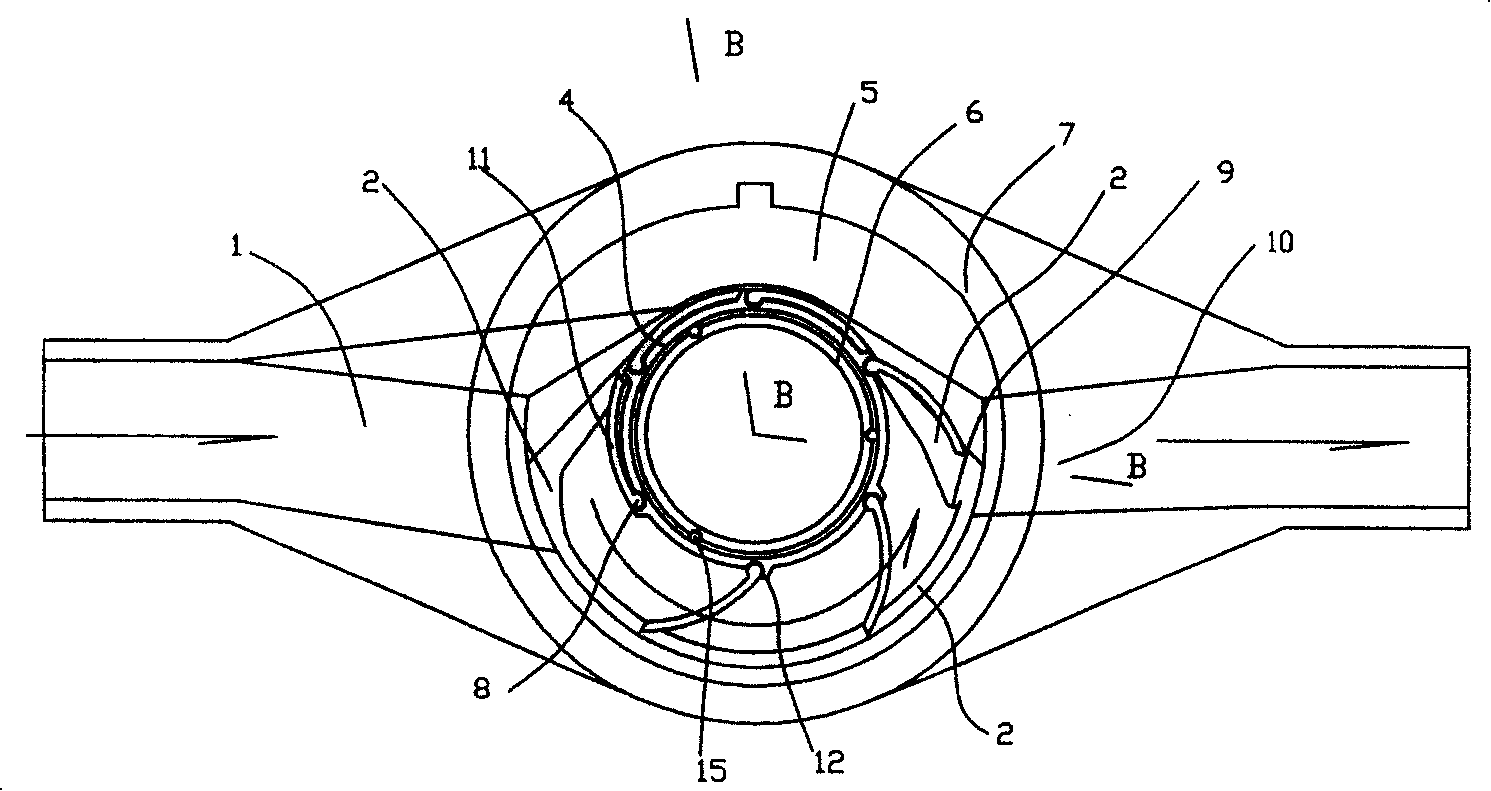
[0025] Such as image 3 , 4 As shown, the difference between the meter body of this kind of variable volume meter and Embodiment 1 is that, firstly, all the blades are set as limiting blades 11, and there is a gap between the head of the limiting blades 11 and the corresponding assembly part of the rotor body 4. The structure 12 for limiting the opening angle of the limiting vane, the opening angle of the limiting vane 11 is between 20° and 90°, and the edge of the tail part is in clearance fit with the inner cavity wall of the meter when it rotates in the metering channel. Secondly, three rolling bearings 15 parallel to the rotation axis of the rotor body are evenly assembled between the sleeve shaft 6 and the rotor body 4 .

Embodiment 3

[0027] Such as Figure 5 , 6As shown, the meter body of this kind of variable volume meter has an inner cavity bushing 5 made of non-toxic wear-resistant plastic embedded in the meter body shell 7, and the inner cavity of the bushing 5 constitutes the inner cavity of the meter. An impeller device is installed in the middle of the inner cavity of the watch, the key is that the impeller device is a deformable impeller device, and the deformable impeller device consists of the rotor body 4 in the middle and the six blades (which can also be appropriately increased to eight blades) surrounded by the rotor body 4. or ten), each blade head and rotor body 4 are rotated and assembled together, and each blade body can swing around the head to open and close, and the ring around the deformable impeller device is bounded by the fluid inlet 1 and the fluid outlet 10, and the blades The part of the ring that passes from the fluid inlet to the fluid outlet is the metering channel, and the ...


PUM


Abstract

Rotatable impeller set is assembled inside cavity of meter body. The impeller set is deformable set. The deformable impeller set is composed of rotor in middle, and at least three blades end to end. Header of each blade is assembled to the rotor. Body of each blade can be swung and stretched and gathered up. Tracks around impeller set are bounded by liquid inlet and liquid outlet. Partial tracks blade passes from inlet to outlet are as measuring tracks. Partial tracks blade passes from outlet back to inlet are as rotative tracks. Top surface of track is parallel to underside perpendicular to axis of rotation of rotor. Width of rotative track is smaller than width of measuring track. Being in measuring track, each blade is stretched, and plugs measuring track. Under action of liquid, impeller set is rotated. Being in rotative track, each blade is gathered up. The meter body raises measuring accuracy of meter.

Description

technical field [0001] The invention relates to a fluid metering device, in particular to a variable volume meter body of the fluid metering device. Background technique [0002] At present, the impellers of various fluid metering devices have fixed shapes and fixed structures. For the fluid metering device, since the fluid inlet on the high-pressure side is directly connected to the fluid outlet on the low-pressure side, when the fluid needs to flow across the fixed blades at a certain angle and at a certain flow rate, a certain rotational driving force is generated on the impeller, and the impeller rotates to perform metering. If the flow rate is less than a certain set value, although the fluid still flows through the blades, due to the small driving force, the measurement will be inaccurate or even not measured. Contents of the invention [0003] In view of the above problems, the purpose of the present invention is to provide a variable volume meter body to improve t...

Claims


Application Information

Patent Timeline
Patent Type & Authority Patents(China)
IPC IPC(8): G01F1/05G01F15/00
Inventor 陈冠一
Owner 陈冠一
Why Eureka
Try Eureka