Bioelectrically controlled ventilation mode

A ventilation mode, bioelectric technology, applied in mechanical/radiation/invasive therapy, medical science, respirator, etc.

Active Publication Date: 2019-06-25
MAQUET CRITICAL CARE
View PDF10 Cites 2 Cited by
  • Summary
  • Abstract
  • Description
  • Claims
  • Application Information

AI Technical Summary

Problems solved by technology

Another challenge is to ensure that the ventilation

Method used


Image

  • Bioelectrically controlled ventilation mode
  • Bioelectrically controlled ventilation mode
  • Bioelectrically controlled ventilation mode

Examples


Embodiment Construction

[0042] A novel bioelectrically controlled ventilation mode with guaranteed minimum minute ventilation will now be described with reference to exemplary and non-limiting embodiments.

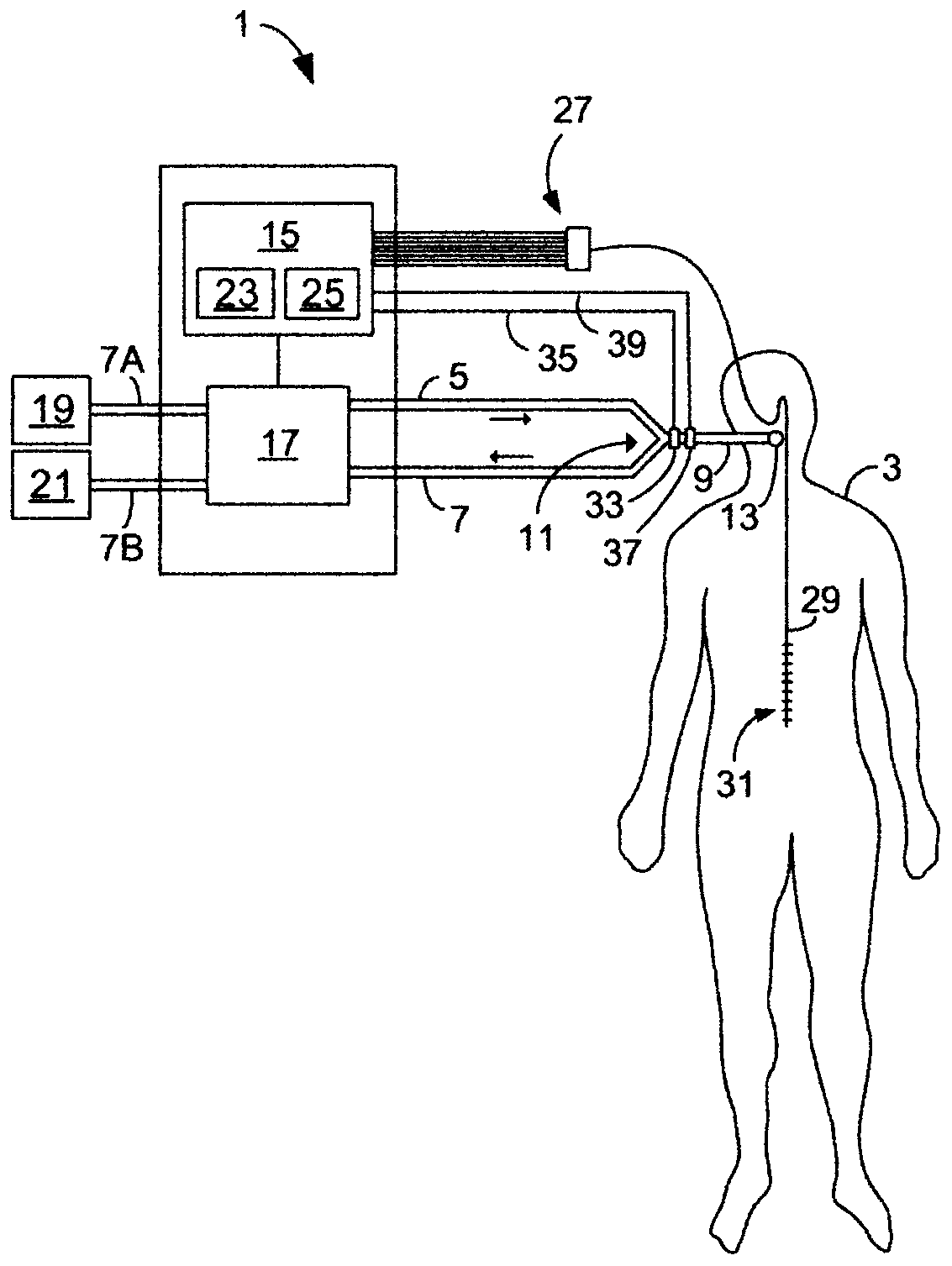
[0043] figure 1 A respiratory device 1 , such as a ventilator or anesthesia machine, is shown for providing ventilation therapy to a patient 3 . The breathing apparatus 1 is connected to the patient 3 via an inspiratory line 5 for supplying breathing gas to the patient 3 and an exhalation line 7 for delivering exhalation gas away from the patient 3 . The inspiratory line 5 and the expiratory line 7 are connected via a so-called Y-piece 11 to a common line 9 which is connected to the patient 3 via a patient connector 13 such as a mask or an endotracheal tube.

[0044] The respiratory device 1 also comprises a control unit 15 for controlling the ventilation of the patient 3 based on preset parameters and / or measurements obtained by various sensors of the respiratory device. The control unit 15 co...


PUM


Abstract

The present disclosure relates to a breathing apparatus (1) configured to provide bioelectrically controlled ventilation to a patient (3) by ventilating the patient in a ventilation mode in which patient-triggered breaths are delivered to the patient upon detection of bioelectrical trigger events indicative of spontaneous breathing efforts by the patient. The breathing apparatus is configured to monitor a level of ventilation of the patient, and to deliver a non-patient triggered breath to the patient when the level of ventilation falls below a minimum ventilation threshold value.

Description

technical field [0001] The present disclosure relates to respiratory apparatus, methods and computer programs for providing bioelectrically controlled ventilation to a patient. Background technique [0002] In the field of mechanical ventilation, there are various techniques for adapting the ventilation pattern provided by the ventilator to the patient's own breathing effort. Ventilation modes in which the ventilator adapts the supply of breathing gas to the detectable breathing effort of the patient being ventilated are generally referred to as assisted or supported ventilation modes. A ventilator operating in such a ventilation mode is said to provide supported ventilation to the patient. [0003] In recent years, techniques have been developed for neuromodulation of ventilation by controlling the supply of breathing gas by the ventilator based on bioelectrical signals indicative of at least the point in time at which the patient desires to inhale and / or exhale so that th...

Claims


Application Information

Patent Timeline
IPC IPC(8): A61M16/00
CPCA61M16/00A61M2016/0015A61M16/0003A61M16/022G16H20/40A61B5/0816
Inventor 奥克·拉松
Owner MAQUET CRITICAL CARE
Why Eureka
Try Eureka