
Residual current monitoring device

A monitoring device and residual current technology, applied in measuring devices, power supply testing, measuring current/voltage, etc., can solve the problems of small magnetic ring width, reduce the effect of residual current monitoring, etc., and achieve a comprehensive monitoring effect

Inactive Publication Date: 2019-06-28
合肥远江电源科技有限公司
View PDF0 Cites 0 Cited by
  • Summary
  • Abstract
  • Description
  • Claims
  • Application Information

AI Technical Summary

Problems solved by technology

[0003] At present, during the detection process of the existing residual current monitoring device, the magnetic ring is generally used to set the wire on the wire. Using the principle of magnetoelectricity, when a residual current is generated somewhere in the wire, due to the change of the magnetic field, the magnetic ring is wound outside. In this way, although the effect of residual current monitoring can be realized, because the wire is located in a place where multiple power equipments are concentrated, there is a certain amount of magnetic field interference around it, and the width of the magnetic ring is small, so it is difficult to detect Each position of the wire is detected, which reduces the effect of residual current monitoring

Method used


Image

  • Residual current monitoring device
  • Residual current monitoring device
  • Residual current monitoring device

Examples


Embodiment Construction

[0030] The following will clearly and completely describe the technical solutions in the embodiments of the present invention with reference to the accompanying drawings in the embodiments of the present invention. Obviously, the described embodiments are only some, not all, embodiments of the present invention. Based on the embodiments of the present invention, all other embodiments obtained by persons of ordinary skill in the art without making creative efforts belong to the protection scope of the present invention.

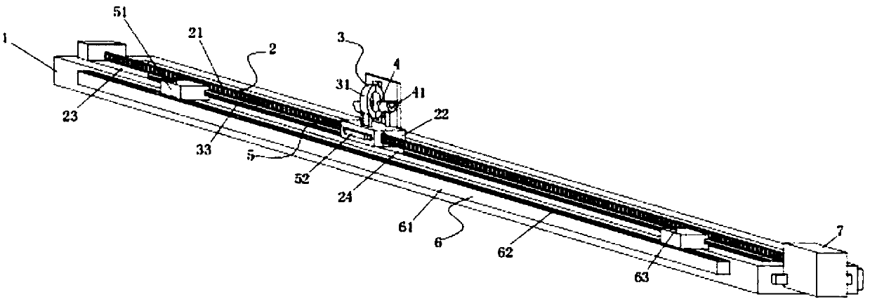
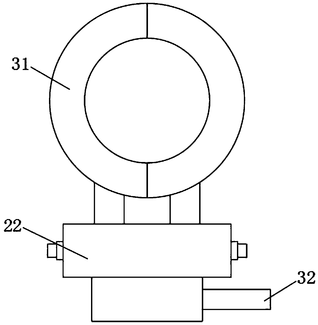
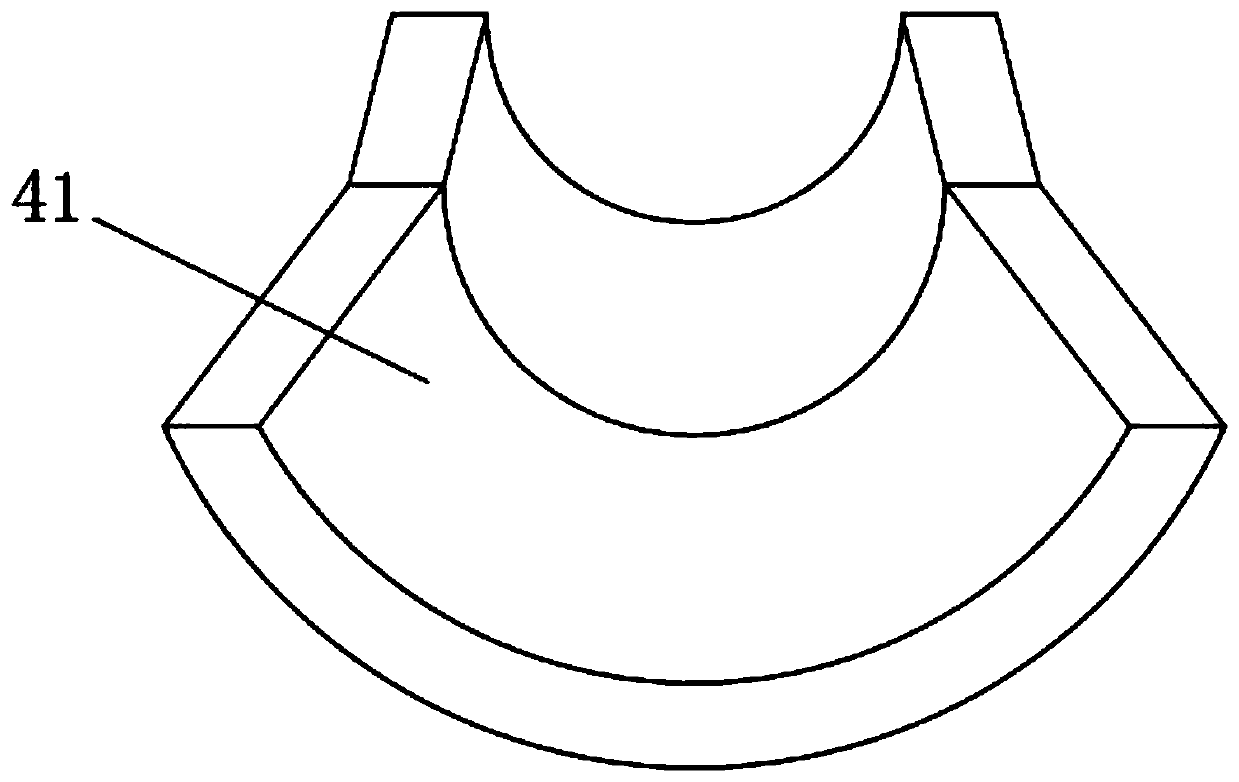
[0031] Such as Figure 1-3 As shown, the present invention provides a technical solution: a residual current monitoring device, comprising:

[0032] The bottom plate 1 is an insulated and non-conductive long strip plate, which is fixedly installed inside the power cabinet during specific use;

[0033] The moving part 2 is arranged on the upper end of the base plate 1. The moving part 2 includes a screw rod 21, a threaded block 22, an orientation groove 23 and...


PUM


Abstract

The invention relates to the technical field of the residual current detection equipment of isolation power supply, and discloses a residual current monitoring device. The monitoring device comprisesa base plate; a moving part arranged at an upper end of the base plate; a monitoring part arranged at an upper end surface of the moving part; a guiding part arranged at the upper end surface of the moving part; a limiting part arranged on the base plate and the moving part and used for limiting the moving distance of the moving part; a regulating part arranged on the base plate and the limiting part and used for regulating a location of the limiting part; and a forward-reverse motor arranged at one end of the base plate. The monitoring device disclosed by the invention can perform comprehensive detection on a conductor along a length direction thereof, and the detection result is improved.

Description

technical field [0001] The invention relates to the technical field of residual current detection equipment for isolated power supplies, in particular to a residual current monitoring device. Background technique [0002] The isolated power supply is a common power supply equipment in medical places. Compared with the transmission power supply, it has the advantage of not being grounded, which greatly improves the safety of use. During the use of the isolated power supply, it needs to integrate a residual current monitoring device inside. It is used for real-time detection of residual current in the circuit loop, and an alarm function is issued when residual current is detected to improve safety efficiency. [0003] At present, in the detection process of the existing residual current monitoring device, the magnetic ring is generally used to set the wire on the wire. Using the principle of magnetoelectricity, when a residual current is generated somewhere in the wire, due to...

Claims


Application Information

Patent Timeline
Patent Type & Authority Applications(China)
IPC IPC(8): G01R19/00G01R31/40
Inventor 徐晓伟
Owner 合肥远江电源科技有限公司
Learn More