Light-emitting unit array and light-emitting part

A light-emitting unit and light-guiding element technology, applied in optical elements, light guides, optics, etc., can solve the problems of poor optical display effect and single luminous effect

Pending Publication Date: 2019-06-28
HASCO VISION TECHNOLOGY CO LTD
View PDF0 Cites 3 Cited by
  • Summary
  • Abstract
  • Description
  • Claims
  • Application Information

AI Technical Summary

Problems solved by technology

[0003] The purpose of this application is to provide a light-emitting unit array and a light-emitting part including the light-emitting unit array, so as to solve the technical problems of single light-emitting effect and poor optical display effect of light-emitting devices in the prior art to a certain extent

Method used


Image

  • Light-emitting unit array and light-emitting part
  • Light-emitting unit array and light-emitting part
  • Light-emitting unit array and light-emitting part

Examples


Embodiment 1

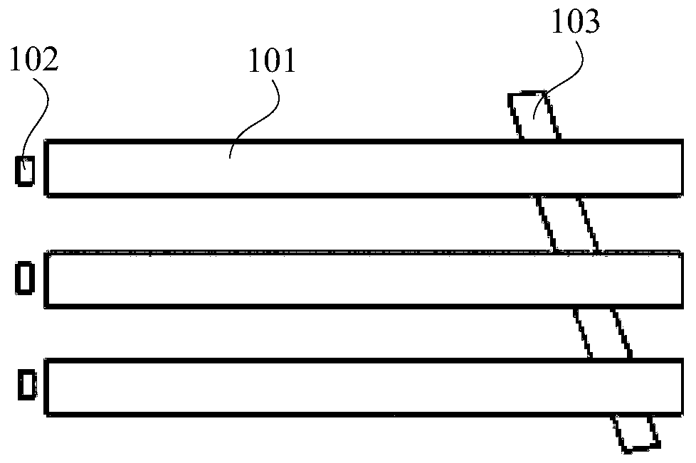
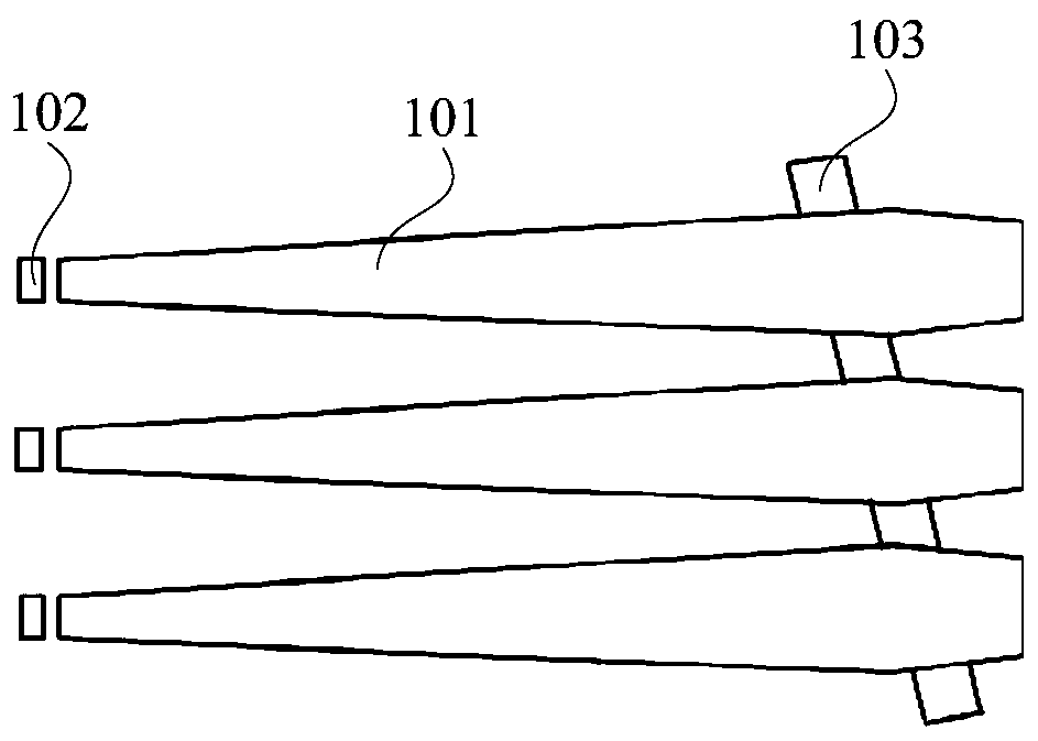
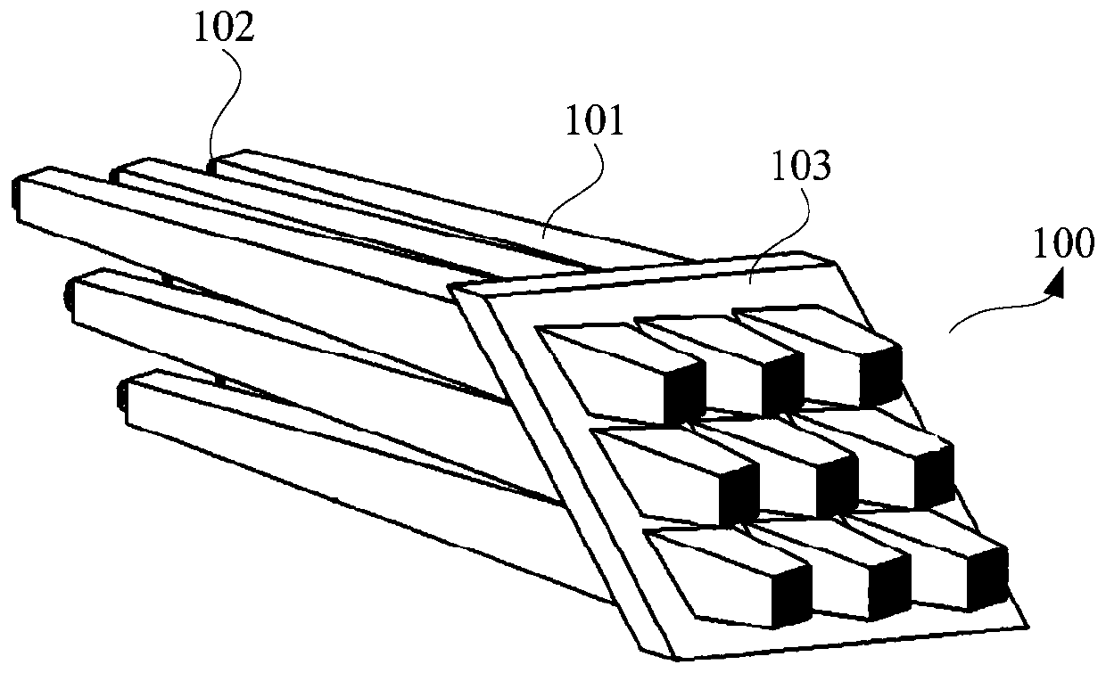
[0036] see Figure 1 to Figure 3 As shown, this embodiment provides a light-emitting unit array 100, including a plurality of light guide elements 101 and a plurality of light sources 102; a plurality of light guide elements 101 are arranged in an array, and the light incident end of each light guide element 101 At least one light source 102 is provided, and each light source 102 is independently controlled.

[0037] The light-emitting unit array 100 of the embodiment of the present application, on the one hand, arranges a plurality of light-guiding elements 101 in an array, so that light-emitting elements of different sizes and shapes can be obtained to meet the size and shape requirements of different light-emitting parts or display parts; on the other hand On the one hand, the light incident end of each light guide element 101 is provided with at least one light source 102, and the light source 102 at the light incident end of each light guide element 101 only provides ligh...

Embodiment 2

[0058] The embodiment of the present application also provides a light-emitting component 200, which includes a plurality of light-emitting unit arrays 100 according to the first embodiment, and the plurality of light-emitting unit arrays 100 are arranged in an array.

[0059] The light-emitting component 200 of this embodiment is assembled by using the light-emitting unit array 100 of the first embodiment, so the technical content of the light-emitting unit array 100 disclosed in the first embodiment will not be described repeatedly, and the content disclosed in the first embodiment also belongs to the disclosure of this embodiment Content.

[0060] The light-emitting part 200 of this embodiment can select the arrangement quantity and mode of the light-emitting array units according to the requirements of the light-emitting effect, and can obtain a light-emitting part 200 whose light-emitting area and arrangement distance are smaller than conventional parts, so more light sour...


PUM


Abstract

The invention relates to the technical field of light-emitting devices, in particular to a light-emitting unit array and a light-emitting part. The light-emitting unit array comprises a plurality of light guide components and a plurality of light sources; the plurality of light guide components are arranged in an array mode; at least one light source is arranged at the light incoming end of each light guide component; each light source is independently controlled. According to the light-emitting unit array, on one hand, the plurality of light guide components are arranged in an array mode andlight-emitting components with different size and models can be obtained, so that the requirements of different light-emitting parts or display parts on the size and the models can be met; on the other hand, at least one light source is arranged at the light incoming end of each light guide component, each light source is independently controlled, and each light source provides only input light rays to the corresponding light guide component, so that each light source can realize single on and off, brightness and color regulation and control on the corresponding light guide components, and thelight-emitting unit array can take on various light-emitting effects and meets different optical display effect requirements.

Description

technical field [0001] The present application relates to the technical field of light emitting devices, in particular to a light emitting unit array and light emitting parts. Background technique [0002] The light-emitting arrays used in existing light-emitting devices are generally controlled by a unified light source for each light-emitting module, so the light-emitting effect is single and the optical display effect is poor. Contents of the invention [0003] The purpose of the present application is to provide a light-emitting unit array and a light-emitting component including the light-emitting unit array, so as to solve the technical problems of single light-emitting effect and poor optical display effect of light-emitting devices in the prior art to a certain extent. [0004] The present application provides a light-emitting unit array, including a plurality of light guide elements and a plurality of light sources; [0005] A plurality of the light guide element...

Claims


Application Information

Patent Timeline
Patent Type & Authority Applications(China)
IPC IPC(8): G09F9/33G02B6/00
Inventor 刘西原陈虎杨珏晶
Owner HASCO VISION TECHNOLOGY CO LTD
Why Eureka
Try Eureka