Shielded metal arc welding system and welding power supply for shielded metal arc welding

A technology of arc welding and welding power supply, which is applied in the direction of arc welding equipment, welding medium, welding equipment, etc. It can solve the problems of low power factor and low phase power factor, and achieve the effect of high power factor

Inactive Publication Date: 2019-07-02
DAIHEN CORP
View PDF1 Cites 1 Cited by
  • Summary
  • Abstract
  • Description
  • Claims
  • Application Information

AI Technical Summary

Problems solved by technology

Even if the power factor in a certain phase is not so low, the power factor in

Method used


Image

  • Shielded metal arc welding system and welding power supply for shielded metal arc welding
  • Shielded metal arc welding system and welding power supply for shielded metal arc welding
  • Shielded metal arc welding system and welding power supply for shielded metal arc welding

Examples


Embodiment Construction

[0071] Preferred embodiments of the present invention will be specifically described below with reference to the drawings.

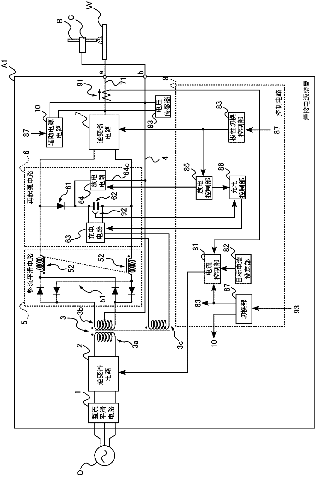
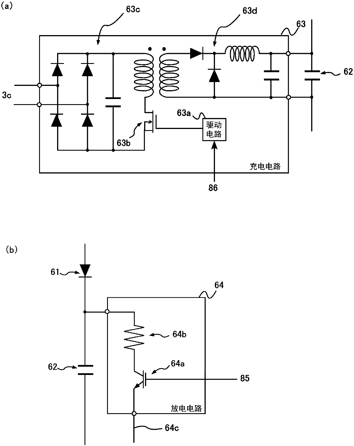
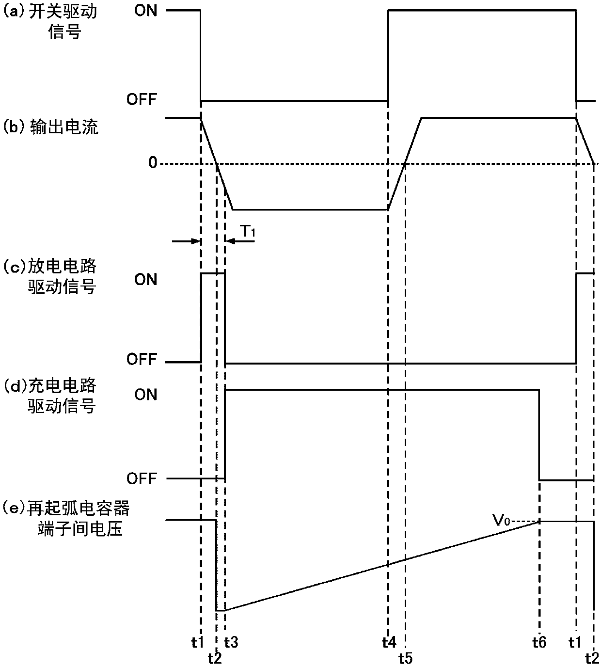
[0072] Figure 1 to Figure 4 It is a figure for demonstrating the covered arc welding system concerning 1st Embodiment. figure 1 It is a block diagram showing the internal structure of the welding power source apparatus A1 which concerns on 1st Embodiment, and shows the whole structure of a covered arc welding system. figure 2 (a) is a circuit diagram which shows an example of the charging circuit 63 of welding power source apparatus A1. figure 2 (b) is a circuit diagram which shows an example of the discharge circuit 64 of welding power supply apparatus A1. image 3 It is a timing chart for explaining the control of the restriking circuit 6, and shows the waveform of each signal of the welding power supply unit A1. Figure 4 It is a waveform diagram showing the waveform of the input current of the welding power supply device according to the first...


PUM


Abstract

The invention provides a shielded metal arc welding system, improving power factor. In a coated arc welding system provided with a coated arc welding rod (B) and a welding power supply device (A1) forsupplying power to the coated arc welding rod (B), the welding power supply device (A1) is provided with: a rectifying and smoothing circuit (5) for converting AC power into DC power; and an invertercircuit (7) for converting the DC power outputted from the rectifying/smoothing circuit (5) into AC power and outputting the AC power to the covered arc welding rod (B). The waveform of the current output from the inverter circuit (7) is rectangular.

Description

technical field [0001] The present invention relates to a covered arc welding system and a welding power supply device for covered arc welding. Background technique [0002] Covered arc welding is known as welding suitable for outdoor work. In covered arc welding, an arc is generated between the tip of a covered arc electrode and a workpiece, and welding is performed using the heat of the arc. In the case of covered arc welding, unlike carbon dioxide gas arc welding and the like, blowing gas is not required. Therefore, welding work can be performed with a simple device. In addition, welding work can be performed even outdoors where gas is blown away by the wind. An example of an AC output covered arc welding system is disclosed in Patent Document 1, for example. [0003] Figure 8 (a) is a block diagram showing an example of a conventional covered arc welding system. Figure 8 The covered arc welding system shown in (a) includes: a covered arc welding electrode B; an ele...

Claims


Application Information

Patent Timeline
IPC IPC(8): B23K9/14B23K9/10B23K9/09
CPCB23K9/092B23K9/1043B23K9/14B23K9/1006B23K35/404B23K9/073B23K9/095
Inventor 宫岛雄一蒲生勇
Owner DAIHEN CORP
Why Eureka
Try Eureka