
Mold stripping ejector pin limitation ejection mechanism

A technology of ejector mechanism and thimble, which is applied in the field of mold ejection ejector pin limit ejection mechanism, which can solve the problems of low production efficiency and the inability of products to fall off automatically, and achieve the effects of reducing labor, saving costs and improving production efficiency

Inactive Publication Date: 2019-07-02
天津中洲志合科技有限公司
View PDF0 Cites 0 Cited by
  • Summary
  • Abstract
  • Description
  • Claims
  • Application Information

AI Technical Summary

Problems solved by technology

After the injection molding is completed, the ejection heights of all the thimbles are the same, resulting in the two thimbles clamping the product, the product cannot fall off automatically, and the robot cannot be used to clamp the product, resulting in low production efficiency

Method used


Image

  • Mold stripping ejector pin limitation ejection mechanism
  • Mold stripping ejector pin limitation ejection mechanism
  • Mold stripping ejector pin limitation ejection mechanism

Examples


Embodiment Construction

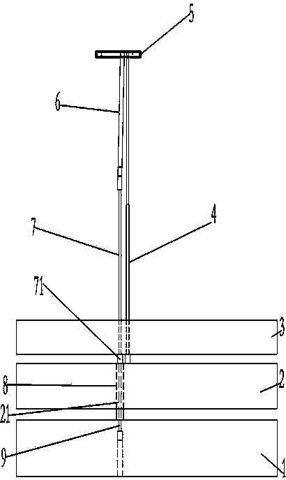
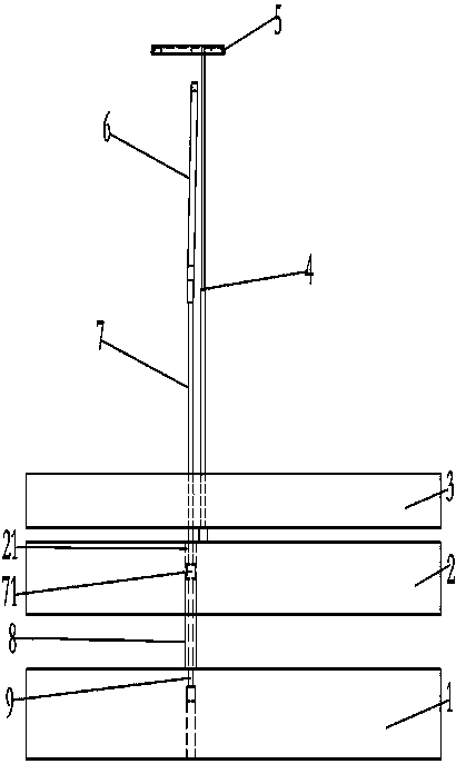
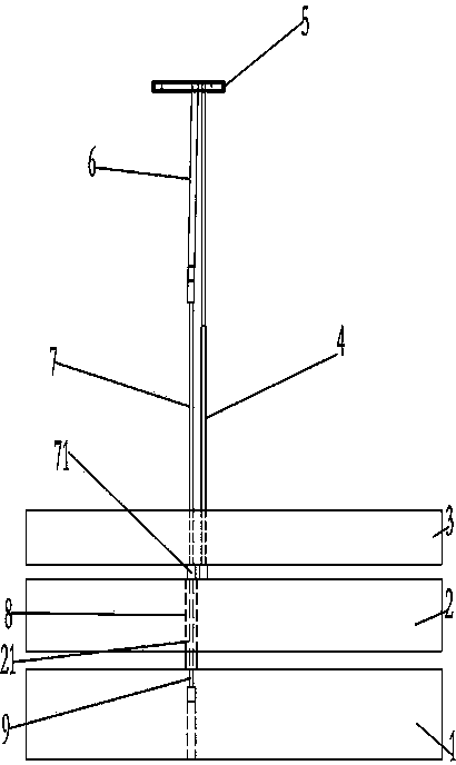
[0009] see Figure 1-Figure 2 , a ejector pin limit ejection mechanism for mold ejection, including ejector pin 7, inclined ejector 6, spring 8 and insert pin 9, inclined ejector 6 is connected to the top of ejector pin 7, insert spring 8 is sleeved on insert pin 9, and the upper end of spring 8 is ejected With the cup head 71 of the thimble 7, the diameter of the via hole 21 of the spring 8 on the thimble base plate 2 is greater than the diameter of the cup head 71. There is also another thimble 4, thimble panel 3, thimble bottom plate 2 and lower fixing plate 1 in the mold, which are used for injection molding products 5.

[0010] When ejecting, use the preload of the spring 8 to push the thimble 7 and the inclined ejector 6 out for a certain distance (the rubber position of the ejected product 5), the spring 8 returns to the original length, and the spring hole 21 on the ejector base 2 Diameter is greater than the diameter of the cup head 71 of thimble 7, and thimble 7 wil...


PUM


Abstract

The invention belongs to the technical field of molds, and provides a mold stripping ejector pin limitation ejection mechanism. The mold stripping ejector pin limitation ejection mechanism comprises an ejector pin. The upper end of the ejector pin is connected with a pitched roof. An insert pin is arranged below a cup head of the ejector pin and further connected with a spring in a sleeved mode. The diameter of the cup head of the ejector pin is smaller than that of a passing hole, located in an ejector pin base plate, of the spring. According to the mold stripping ejector pin limitation ejection mechanism, stopping can be conducted before products are ejected in place, the condition that the products are clamped by two ejector pins is avoided, and therefore mechanical arms can be used, production efficiency is improved, and manual work and cost are reduced.

Description

technical field [0001] The invention relates to an ejection mechanism of a mold, in particular to an ejection mechanism for limiting ejector pins of a mold ejection. Background technique [0002] During the injection molding process, some products require two thimbles. After the injection molding is completed, the ejection heights of all the thimbles are the same, resulting in the two thimbles clamping the product, the product cannot fall off automatically, and the robot cannot be used to clamp the product, resulting in low production efficiency. Contents of the invention [0003] The purpose of the present invention is to overcome the deficiencies of the prior art, and to provide a limit ejection mechanism for ejection pins of molds. [0004] For realizing above object, the technical scheme that the present invention adopts is: [0005] A mold release ejector pin limit ejection mechanism, comprising an ejector pin, the upper end of the ejector pin is connected with a sl...

Claims


Application Information

Patent Timeline
IPC IPC(8): B29C45/40
CPCB29C45/401
Inventor 不公告发明人
Owner 天津中洲志合科技有限公司
Learn More