A method for assembling high and low temperature vacuum stepping motors

A low-temperature vacuum and stepping motor technology, applied in the manufacture of motor generators, electromechanical devices, electrical components, etc., can solve the problems of uneven pressure on the magnetic steel, damage to the stator or motor shell, and large impact, and achieve guaranteed Accuracy, easy installation results

Active Publication Date: 2020-04-07
成都金士力科技有限公司
View PDF3 Cites 0 Cited by
  • Summary
  • Abstract
  • Description
  • Claims
  • Application Information

AI Technical Summary

Problems solved by technology

[0007] The purpose of the present invention is to: in the assembly process of the high and low temperature stepper motor existing in the prior art, when the assembly of the rotor 3 and the assembly of the stator assembly are placed in the same equipment, the stator, the motor housing or the The iron core of the samarium-cobalt magnet is easy to be damaged under the condition of uneven pressure or excessive impact. Provide a method for assembling high and low temperature vacuum stepping motors. During the assembly process of high and low temperature stepping motors , when the assembly of the rotor and the assembly of the stator assembly are placed on the same equipment, the assembly accuracy requirements are met, and at the same time, during the assembly process of the rotor, it is avoided due to the same The axiality is out of tolerance, which causes the magnetic steel near the center through hole on the iron core to be cracked due to uneven pressure and excessive impact in some areas, and during the assembly process of the stator assembly, avoid stator Or the pressure on the motor casing is uneven, and some areas have too much impact, resulting in damage to the stator or the motor casing

Method used


Image

  • A method for assembling high and low temperature vacuum stepping motors
  • A method for assembling high and low temperature vacuum stepping motors
  • A method for assembling high and low temperature vacuum stepping motors

Examples


Embodiment 1

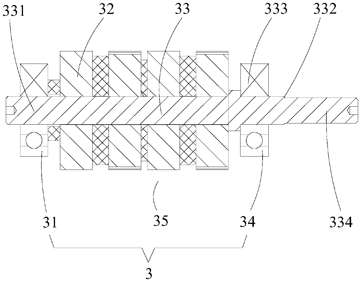
[0082] like Figure 1-8 As shown, a method for assembling a high and low temperature vacuum stepper motor includes the following steps:

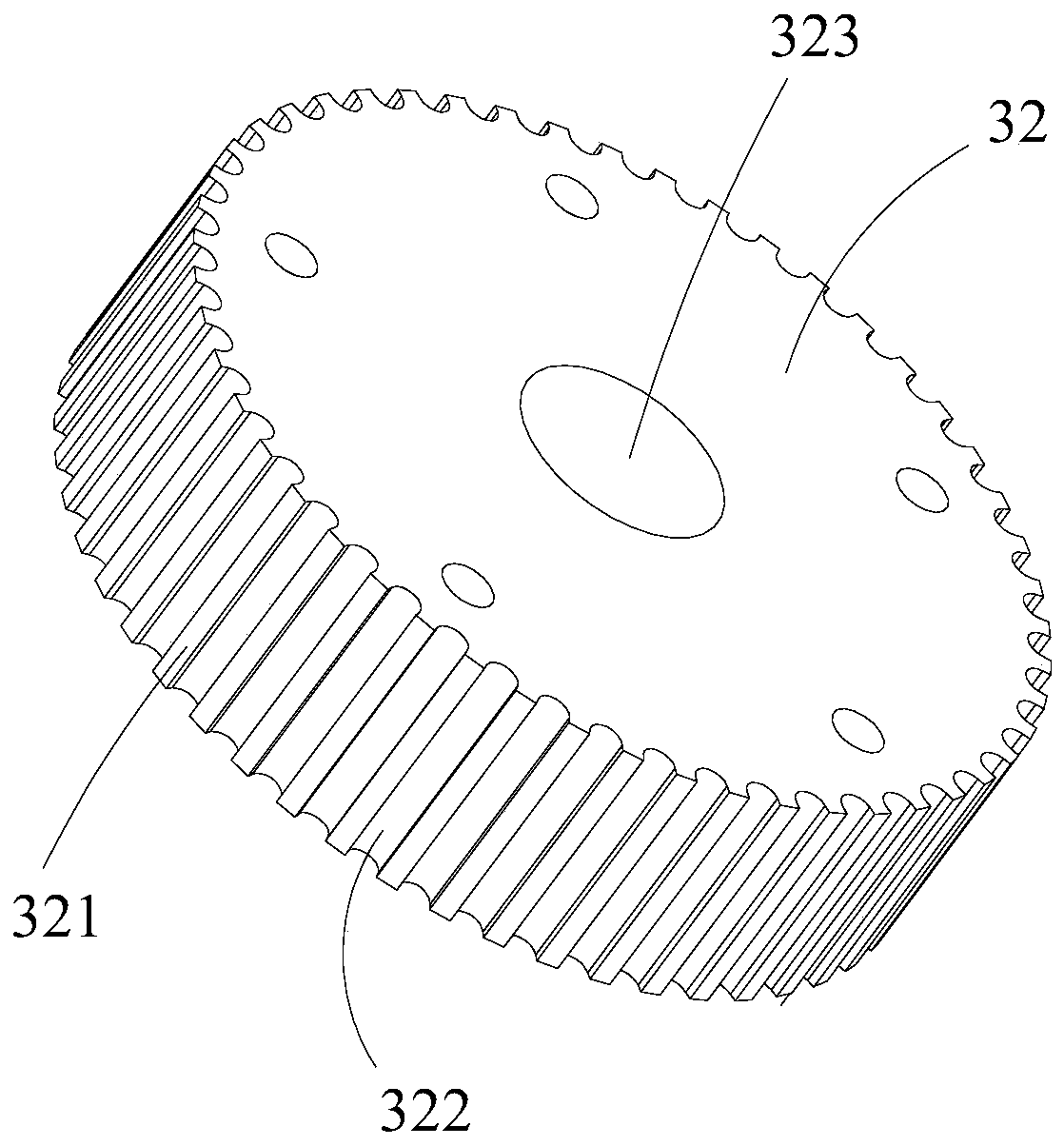
[0083] Step 1. Install the rotating shaft 33 on the first tooling 12, the first tooling 12 is installed on the moving plate 114, the iron core 32 is installed on the second tooling 13, and the second tooling 13 is installed on the support 11 On the upper side, the electric cylinder 2 is connected to the moving plate 114, the electric cylinder 2 is arranged vertically, the moving plate 114 is slidingly fitted with the support 11 along the axis direction of the electric cylinder 2, the rotating shaft 33, The iron core 32 and the electric cylinder 2 are coaxially arranged, the electric cylinder 2 drives the moving plate 114 to slide relative to the support 11 , and the rotating shaft 33 and the iron core 32 are assembled to form a rotor. Iron core assembly 35;

[0084] Step 2: Remove the second tooling 13 and the rotor core assembly 35, then ...

Embodiment 2

[0091] like Figure 1-8 As shown, a method for assembling a high and low temperature vacuum stepping motor as described in Embodiment 1, the electric cylinder 2 is connected with a control system 6, and the control system 6 is used to control the action of the electric cylinder 2 , the control system 6 is electrically connected with the electric cylinder 2, and the control system 6 includes a control module 61 and an HMI module 62, wherein,

[0092] The HMI module 62 is used to provide an interactive interface between the control system 6 and the user, including receiving instructions from the user, transmitting the instructions input by the user to the control module 61, and displaying the electric cylinder 2 displacement results;

[0093] The control module 61 controls the electric cylinder 2 to drive the moving plate 114 to move to a predetermined position according to the instruction, and the control module 61 is electrically connected to the electric cylinder 2 and the H...

Embodiment 3

[0100] like Figure 1-8 As shown, according to a method for assembling a high-low temperature vacuum stepping motor described in Embodiment 1 or 2, the support 11 includes an upper seat plate 111 and a lower seat plate 112, the upper seat plate 111 and the lower seat plate 111 A sliding rod 113 is connected between the seat plates 112 , and the moving plate 114 is slidably matched with the sliding rod 113 along the axis direction of the electric cylinder. The electric cylinder 2 includes a cylinder barrel 21 and a movable rod 22 . The upper seat plate 111 is connected with the cylinder 21 , and the moving plate 114 is connected with the movable rod 22 .

[0101] Based on the above, in a further preferred manner, there are four sliding rods 113 , all the sliding rods 113 are distributed on the same circumference on the lower seat plate 112 , and all the sliding rods 113 are parallel to each other.

[0102] Four sliding rods 113 are distributed around the circumference, and all...


PUM


Abstract

The invention relates to the technical field of stepping motor assembling and particularly relates to a method for assembling a high and low temperature vacuum stepping motor. The method comprises steps that a rotation shaft and a core are assembled; an upper bearing and a lower bearing are simultaneously assembled with the rotation shaft; a stator is assembled with a motor casing. The method is advantaged in that under the condition that a rotor and the stator assembly are assembled at the same device, assembling accuracy requirements are satisfied, moreover, in the rotor assembling process,a problem that a magnetic steel near a center through hole on the core is uneven in force bearing due to overproof coaxiality among the upper bearing, the core, the rotation shaft and the lower bearing is avoided, a problem of avulsion due to overlarge regional impact is avoided, and in the assembling process of the stator assembly, a problem of damage to the stator or the motor casing caused by the overlarge regional impact due to uneven force borne by the stator or the motor casing is avoided.

Description

technical field [0001] The invention relates to the technical field of stepper motor assembly, in particular to a method for assembling a high and low temperature vacuum stepper motor. Background technique [0002] like figure 1 and 2 As shown, at present, the rotor 3 of the high-low temperature stepping motor consists of a rotating shaft 33 and a number of iron cores 32 and other main parts. A number of rotating teeth 321 are provided on the outer side of the iron core 32. On the same iron core 32, adjacent rotating teeth A groove 322 is formed between 321; the shaft 33 is coaxially provided with a journal head end 331, a journal tail end 333 and a shaft extension 334, and the journal tail end 333 is arranged on the journal head end 331 and the shaft extension 334 In between, the diameters of the journal head end 331 and the journal tail end 333 are the same, the diameter of the shaft extension 334 is smaller than the diameter of the journal tail end 333, and the connecti...

Claims


Application Information

Patent Timeline
Patent Type & Authority Patents(China)
IPC IPC(8): H02K15/00
CPCH02K15/00
Inventor 邓浩宇吴顺辉王凤鸣
Owner 成都金士力科技有限公司
Why Eureka
Try Eureka