Installation trailer for coiled flexible pipe and method of utilizing same

A trailer and coil technology, applied in the field of trailer frame and coil system, can solve the problem of large tube coil

Active Publication Date: 2019-07-09
TRINITY BAY EQUIP HLDG LLC
View PDF15 Cites 7 Cited by
  • Summary
  • Abstract
  • Description
  • Claims
  • Application Information

AI Technical Summary

Problems solved by technology

Coils of pipe are currently loaded and transported using different types of devices and vehicles, but often additional equipment and hu

Method used


Image

  • Installation trailer for coiled flexible pipe and method of utilizing same
  • Installation trailer for coiled flexible pipe and method of utilizing same
  • Installation trailer for coiled flexible pipe and method of utilizing same

Examples


Embodiment Construction

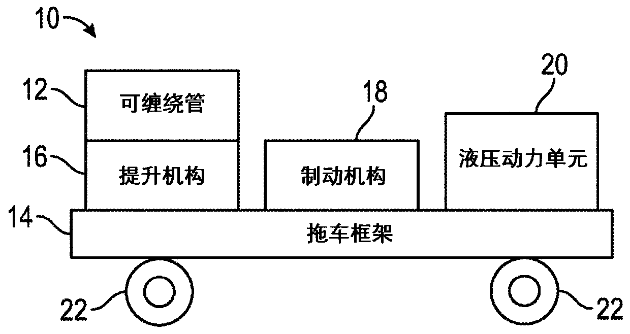
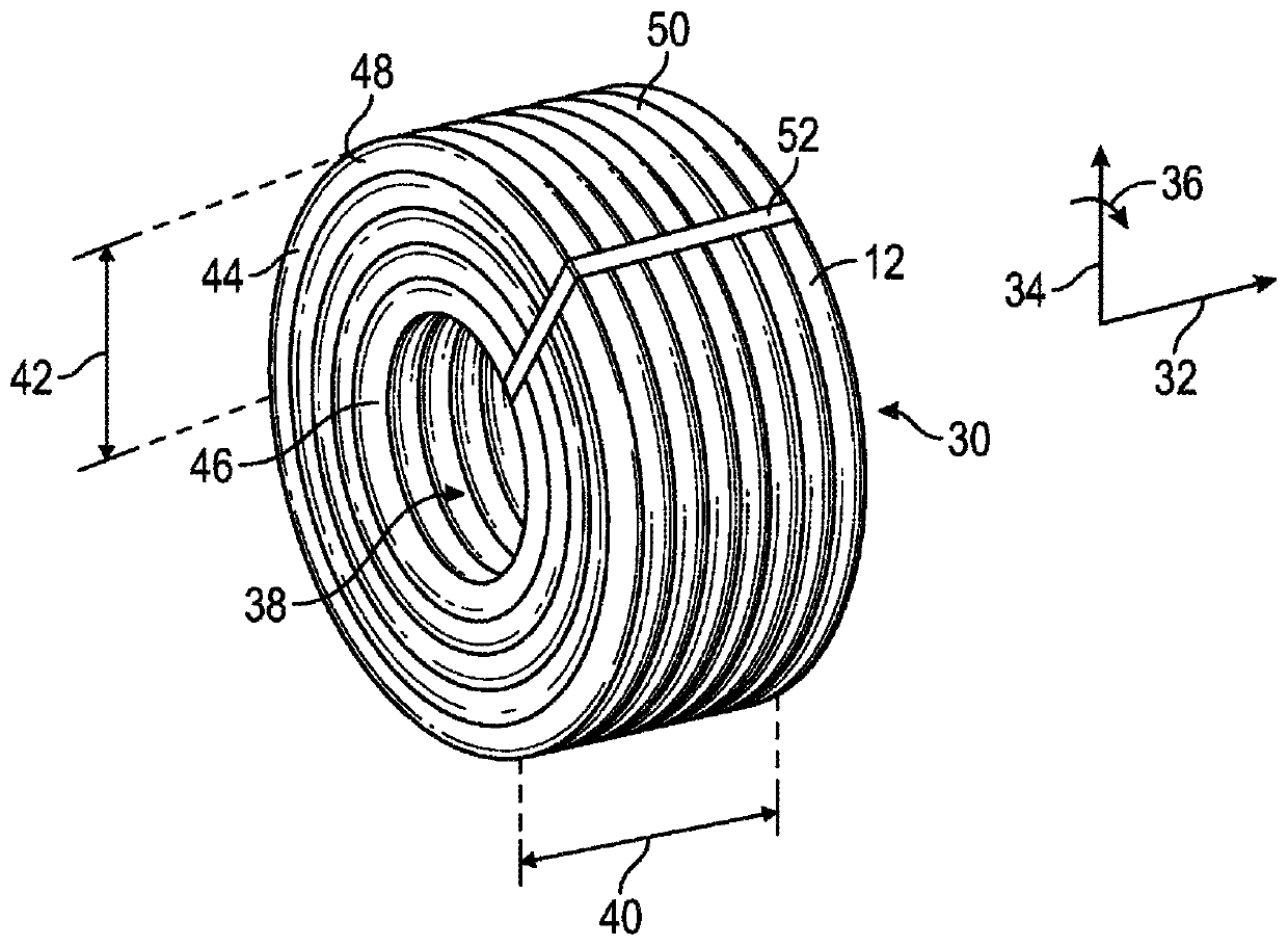
[0035] Embodiments of the present disclosure generally relate to systems for unrolling coils of flexible pipe. The coils of tube may be self-supporting, for example, using straps to hold the coils together. The coil of tube may be self-supporting, for example, using straps to hold the coil together, or the coil of tube may be supported around a roll (which may be referred to as a roll of tube). A deployment system according to embodiments of the present disclosure may include a mounting trailer that includes a trailer frame; a lift mechanism coupled to the trailer frame that is configured to raise or lower a coil of tubing or a spool of tubing; a braking mechanism that a hydraulic power unit configured to hydraulically power the system configured to apply pressure to the tube as it is deployed by the system; and a hydraulic power unit configured to hydraulically power the system.

[0036] Embodiments of the present disclosure will be described below with reference to the draw...


PUM


Abstract

A system includes a trailer frame, a lifting mechanism coupled to the trailer frame, wherein the lifting mechanism is configured to raise or lower a coil of pipe or a reel of pipe, a braking mechanismconfigured to apply pressure to the pipe while the pipe is being deployed by the system, and a hydraulic power unit configured to hydraulically power the system.

Description

[0001] Cross References to Related Applications [0002] This application claims the benefit and priority of US Provisional Application 62 / 406,231, filed October 10, 2016, the disclosure of which is incorporated herein by reference in its entirety. Background technique [0003] Flexible pipe is useful in a myriad of environments, including in the oil and gas industry. Flexible pipe can be durable and can operate under harsh operating conditions and can accommodate high pressure and high temperature. Flexible tubing can be bundled and arranged in one or more coils to facilitate transportation and use of the tubing. [0004] The coils of tube may be positioned with an "eye to the side" or an "eye to the sky" orientation. A coil of flexible pipe is said to be in a "eye-to-sky" orientation when the flexible pipe is coiled with its internal passageway facing upwards so that the coil is in a horizontal orientation. Conversely, if the flexible pipe is coiled and positioned so that...

Claims


Application Information

Patent Timeline
IPC IPC(8): B65H75/42B60P1/16B60P1/26B60P3/035B62D63/06B65H49/38
CPCB65H67/02B65H2701/33B60P3/035B65H49/32B65H59/06B62D63/061B60P1/162B65H75/32B60P1/025
Inventor A·R·巴奈特M·A·海格勒
Owner TRINITY BAY EQUIP HLDG LLC
Why Eureka
Try Eureka