Portable welding wire feed system and method

a wire feeder and portable technology, applied in the direction of welding coupling means, manufacturing tools, electrode supporting devices, etc., can solve the problems of inconvenient carrying, inconvenient operation, and the need for a more robust and expensive drive mechanism of the wire feeder,

Active Publication Date: 2010-03-04
ILLINOIS TOOL WORKS INC
View PDF62 Cites 110 Cited by
  • Summary
  • Abstract
  • Description
  • Claims
  • Application Information

AI Technical Summary

Problems solved by technology

Portable welding systems may be used in field applications where it is not practical or convenient to send a work piece to a welding shop for repair or fabrication.
Otherwise, the wire feeder may be required to drive the wire over an unnecessarily long run of conduit to the particular location.
As a result, the wire feeder may require a more robust and expensive drive mechanism.
Unfortunately, conventional wire feeders are designed as stationary devices intended to remain within a particular work area.
Additionally, conventional portable wire feeders can be difficult or impossible to carry in areas requiring one or both hands of the user.
However, these wire feeders and torches may result in a bulky and heavy torch that is difficult to hold, maneuver, and weld in certain locations, and the wire feeder torches may be up to 10 to 15 feet in length.
The wire feed mechanisms and control circuitry in these wire feeders may also add cost and manufacturing complexities.
Additionally, wire welders, conventional portable wire feeders, or the torch and wire feeder units, may be too heavy or bulky to move effectively.

Method used


Image

  • Portable welding wire feed system and method
  • Portable welding wire feed system and method
  • Portable welding wire feed system and method

Examples


Embodiment Construction

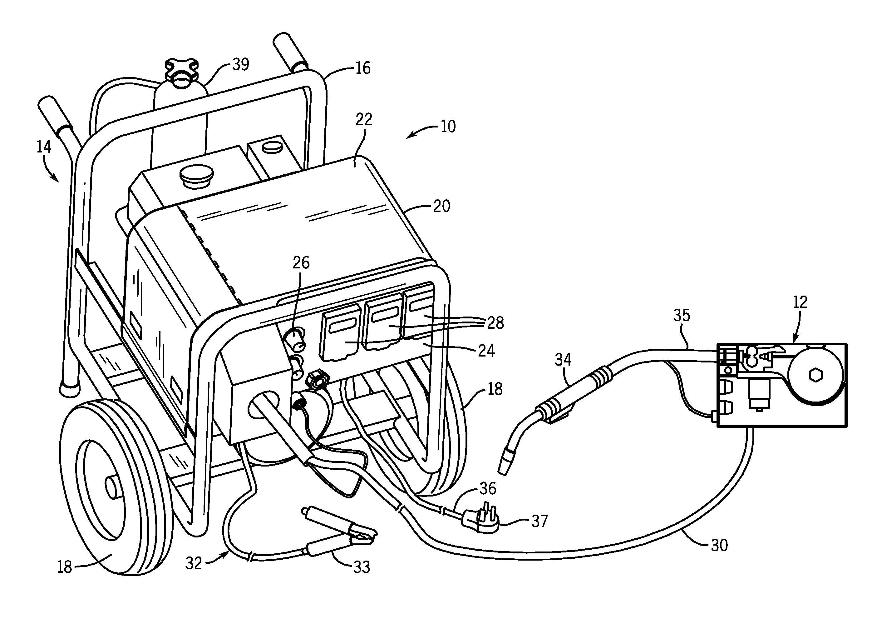
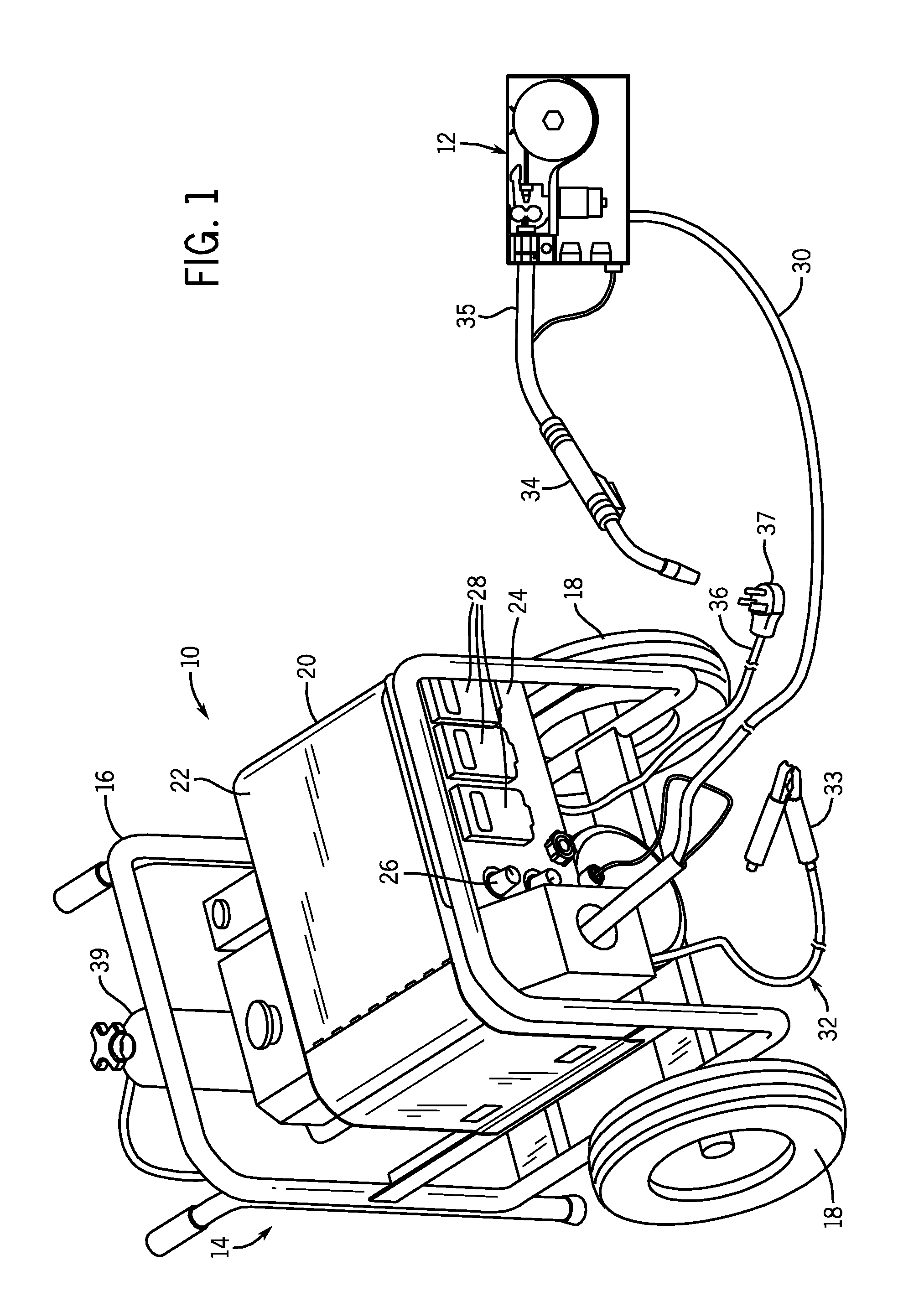
[0013]FIG. 1 is a perspective view of a portable engine-driven welding system 10 coupled to a wearable wire feeder 12 in accordance with an embodiment of the present invention. The illustrated system 10 is a metal inert gas (MIG) welding system, although other welding systems may utilize the wearable wire feeder 12 discussed below. As illustrated in FIG. 1, welding system 10 may include a cart or other portable assembly, as indicated generally by reference numeral 14. In the illustrated embodiment, the cart 14 has a tubular frame 16 with wheels 18 for easily moving the cart 14 from place to place. The components described in FIG. 1 and discussed below are generally mounted in an enclosure 20 comprising a number of panels 22 which can be removed or displaced to access the components within the cart 14. A front panel 24 includes various controls and cable connections. The front panel 24 includes a control panel 26 where the various adjustments can be made for setting the regime of the...


PUM

PropertyMeasurementUnit
lengthaaaaaaaaaa
rated poweraaaaaaaaaa

Abstract

A welding system is provided that includes a wearable wire feeder having a wire drive motor that is responsive to a control signal received directly from a power unit. Another welding system is provided that includes a wearable wire feeder that is configured to couple to a constant voltage power unit and does not include a voltage sensor. Another welding system is provided that includes a power unit, a wearable wire feeder separate from the power unit, a cable extending directly from the power unit to the wearable wire feeder and a welding torch coupled to and separate from the wire feeder. A method is provided that includes receiving a control signal from a power unit at a wearable wire feeder and driving a welding wire from the wearable wire feeder to a welding torch in response to the control signal, wherein the wearable wire feeder is separate from the torch.

Description

BACKGROUND[0001]The invention relates generally to portable welding systems. More specifically, embodiments of the invention relate to a wearable wire feeder having various components integrally mounted inside a wearable unit.[0002]Portable welding systems may be used in field applications where it is not practical or convenient to send a work piece to a welding shop for repair or fabrication. These welding systems find applications in the farming and ranching industry and in a variety of other settings. To provide the welding functionality, a welding wire feeder may be used to feed a welding wire through a torch to a molten weld location in front of the tip of the torch. In many applications, it may be desirable to move the wire feeder to a remote location or to a different location in a work area. Otherwise, the wire feeder may be required to drive the wire over an unnecessarily long run of conduit to the particular location. As a result, the wire feeder may require a more robust ...

Claims


Application Information

Patent Timeline
Patent Type & Authority Applications(United States)
IPC IPC(8): B23K9/28
CPCB23K9/1336B23K9/323B23K9/32
Inventor DIEDRICK, MICHAEL G.BAETEN, GREGORY C.
Owner ILLINOIS TOOL WORKS INC
Why Eureka
Try Eureka