Double-shaft mechanical arm for paper deacidification
A technology of mechanical arms and manipulators, applied in manipulators, program-controlled manipulators, waste paper post-processing, etc., can solve the problems that the quality of deacidification is greatly affected by human factors, the consumption of deacidification solution cannot be adjusted, and it is not suitable for long-term work. , to achieve the effect of improving spraying efficiency, controllable speed and reducing working time
- Summary
- Abstract
- Description
- Claims
- Application Information
AI Technical Summary
Problems solved by technology
Method used
Image
Examples
Embodiment 1
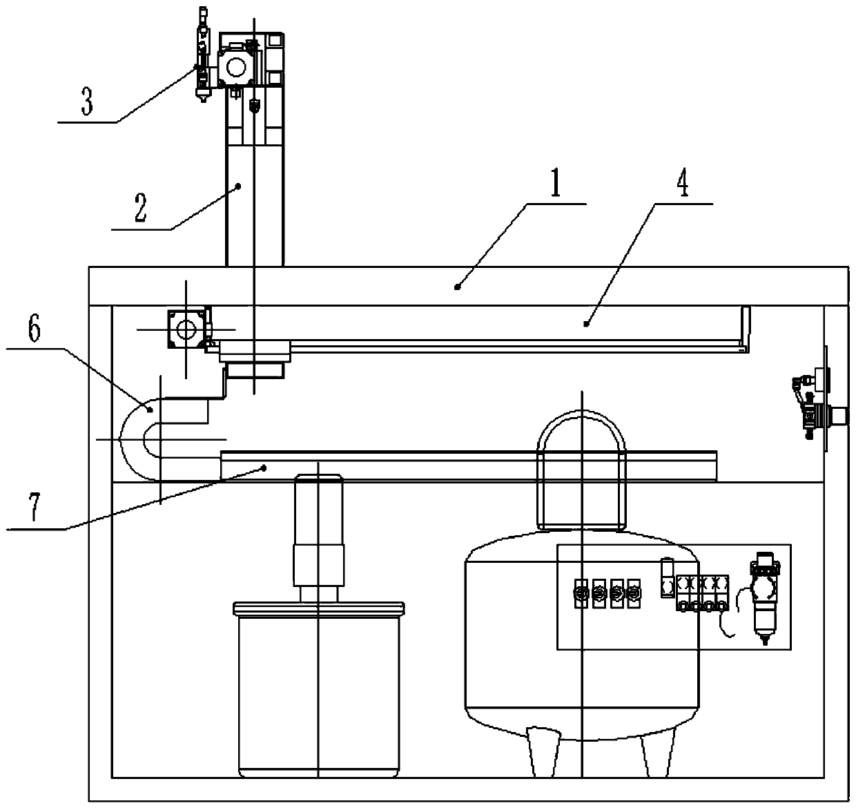
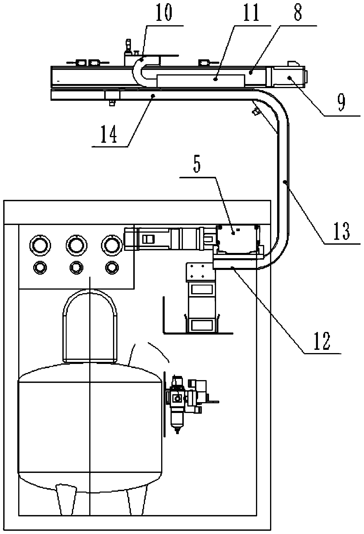
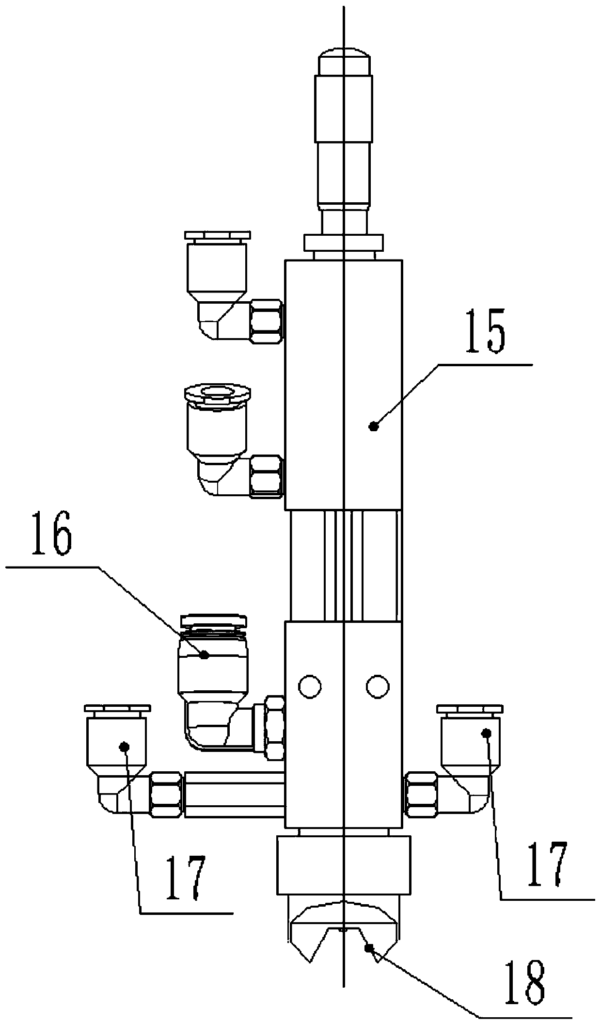
[0023] Such as figure 1 and 2 Shown, a kind of paper deacidification is used biaxial manipulator, comprises workbench 1, is provided with the X-axis manipulator that runs along the long side direction of workbench 1 at the bottom of workbench 1, is provided with along the upper part of workbench 1 The Y-axis manipulator running in the width direction of the workbench 1, the X-axis manipulator and the Y-axis manipulator are connected by a U-shaped bracket 2 arranged horizontally, the bottom of the U-shaped bracket 2 is connected with the X-axis manipulator, and the Y-axis manipulator is installed On the top of the U-shaped support 2, the Y-axis manipulator can move with the X-axis manipulator under the drive of the U-shaped support 2, and the Y-axis manipulator is equipped with a nozzle 3 for spraying deacidification liquid. Such as image 3 As shown, the spray nozzle 3 includes a nozzle 15, the side wall of the nozzle 15 is connected with a deacidification liquid inlet 16 an...
Embodiment 2
[0030] Such as figure 1As shown, this implementation is further optimized on the basis of Embodiment 1. This embodiment focuses on the improvements compared with Embodiment 1, and the similarities will not be repeated. In this embodiment, the U-shaped bracket 2 includes the first segment rod 12, the second segment rod 13 and the third segment rod 14 which are all provided with cavities, the first segment rod 12 is connected to the first linear module 4 horizontally, and the second segment rod 13 is vertical The straight connection is on the first segment rod 12, the third segment rod 14 is horizontally connected on the second segment rod 13 and the third segment rod 14 is arranged above the workbench 1, the spray head 3 and the second linear module 8 are arranged on the third segment rod 14 respectively. It is convenient for the trachea and the infusion tube of the nozzle 3 to pass through the cavity to play the role of traction and protection.
Embodiment 3
[0032] Such as figure 1 As shown, this implementation is further optimized on the basis of Embodiment 1. This embodiment focuses on the improvements compared with Embodiment 1, and the similarities will not be repeated. In this embodiment, the first section of the rod A first chamfer is provided at the joint between 12 and the second section of rod 13 , and a second chamfer is provided at the connection between the second section of rod 13 and the third section of rod 14 . The setting of the first chamfer and the second chamfer can prevent the connection between the first section of rod 12 and the second section of rod 13 and the connection between the second section of rod 13 and the third section of rod 14 Blocked by edges and corners, it knots and blocks the pipeline of the infusion tube, resulting in weakening of the liquid coming out of the nozzle 3 and affecting the spraying effect.
PUM
 Abstract
Description
Claims
Application Information
 - R&D
- Intellectual Property
- Life Sciences
- Materials
- Tech Scout
- Unparalleled Data Quality
- Higher Quality Content
- 60% Fewer Hallucinations
Browse by: Latest US Patents, China's latest patents, Technical Efficacy Thesaurus, Application Domain, Technology Topic, Popular Technical Reports.
© 2025 PatSnap. All rights reserved.Legal|Privacy policy|Modern Slavery Act Transparency Statement|Sitemap|About US| Contact US: help@patsnap.com


