
Mold ejection mechanism

A technology of ejection mechanism and mold, which is applied in the field of injection molding machines, and can solve problems such as scratched products and damaged thimbles

Active Publication Date: 2022-02-11
苏州优瑞信电子科技有限公司
View PDF0 Cites 0 Cited by
  • Summary
  • Abstract
  • Description
  • Claims
  • Application Information

AI Technical Summary

Problems solved by technology

[0005] Therefore, the technical problem to be solved by the present invention is to overcome the mold ejection mechanism in the prior art after the product is ejected from the mold, because the ejector device is always in contact with the product, and when the product is automatically pulled, it is easy to cause Scratch the product or damage the thimble itself, so as to provide a mold ejection mechanism that can withdraw the thimble in time after the product is ejected

Method used


Image

  • Mold ejection mechanism
  • Mold ejection mechanism
  • Mold ejection mechanism

Examples


Embodiment Construction

[0074] The technical solutions of the present invention will be clearly and completely described below in conjunction with the accompanying drawings. Apparently, the described embodiments are some of the embodiments of the present invention, but not all of them. Based on the embodiments of the present invention, all other embodiments obtained by persons of ordinary skill in the art without making creative efforts belong to the protection scope of the present invention.

[0075] In the description of the present invention, it should be noted that the orientation or positional relationship indicated by the terms "upper", "lower", "left", "right", "inner" and "outer" are based on the Orientation or positional relationship is only for the convenience of describing the present invention and simplifying the description, and does not indicate or imply that the referred device or element must have a specific orientation, be constructed and operated in a specific orientation, and thus s...


PUM


Abstract

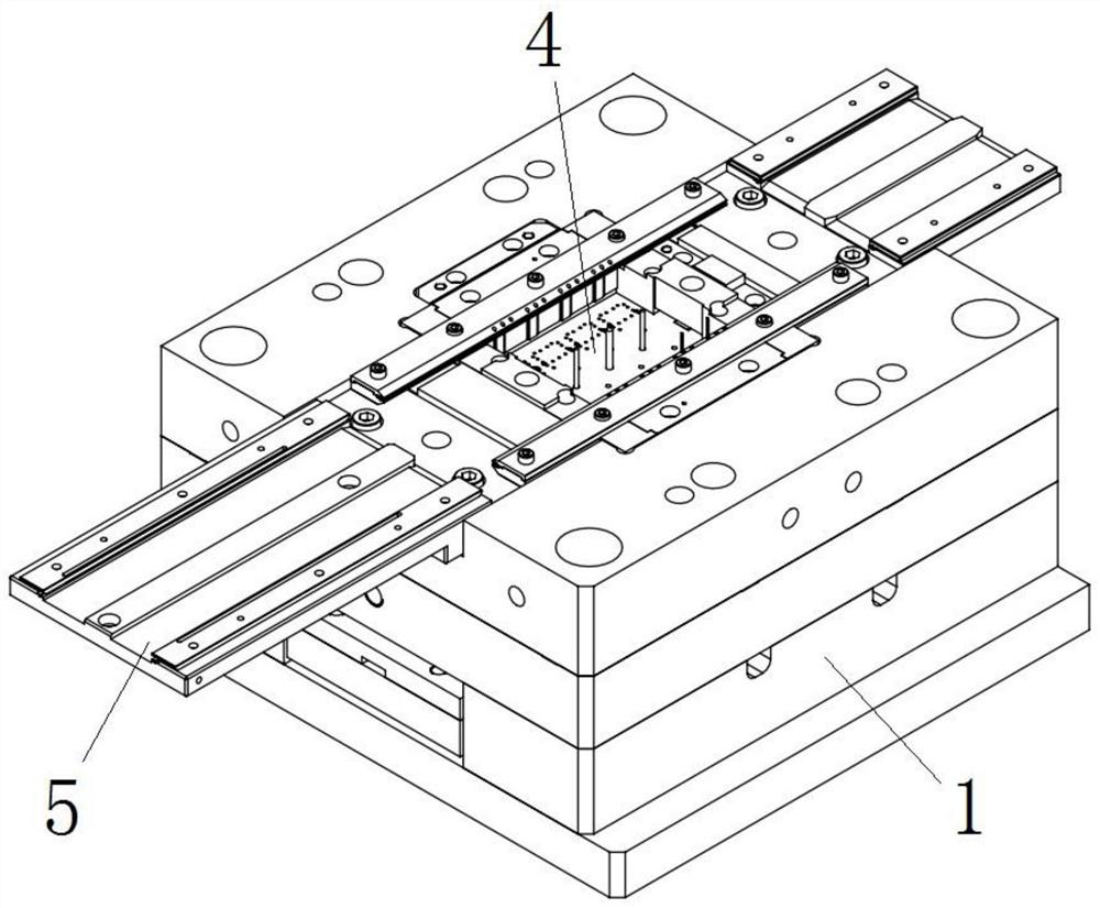
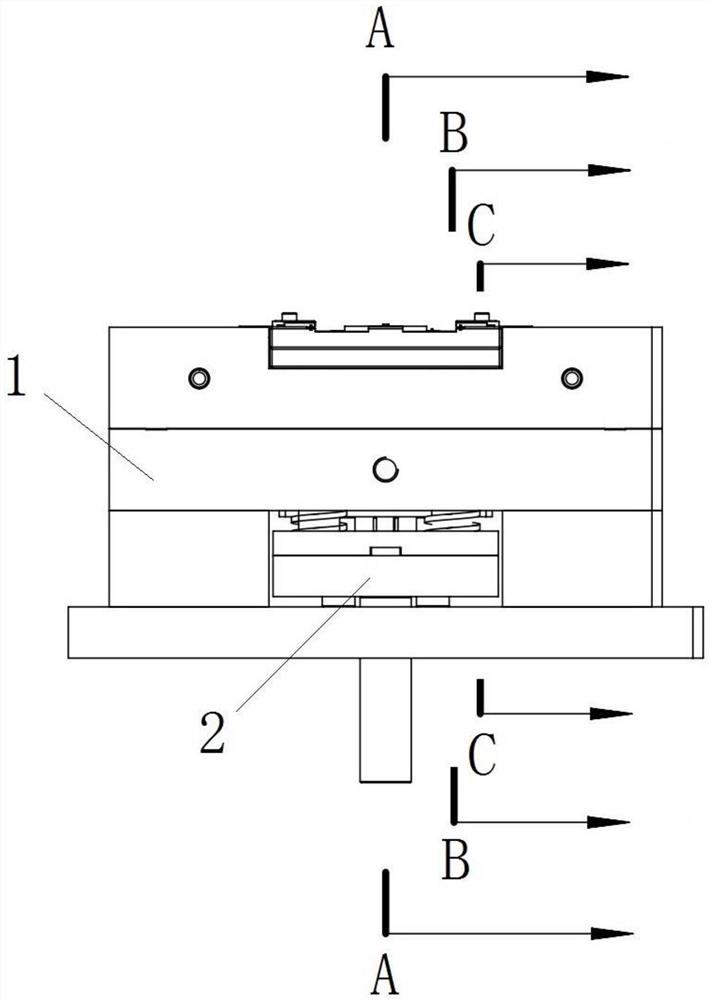
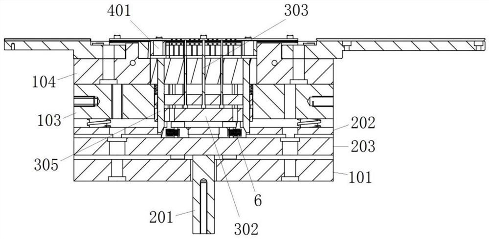
The invention provides a mold ejection mechanism, which includes a shell, a top plate mechanism, a floating plate mechanism and a sliding structure. During the process of abutting against the floating plate mechanism, the sliding structure reaches a preset position by sliding, and at the preset position, Release the resistance to the floating plate mechanism, so that the floating plate mechanism retracts and moves under the action of the return spring, and drives the ejector device to retract together; the mold ejecting mechanism of the present invention, the top plate mechanism in the housing and The sliding structure provided between the floating plate mechanisms is used to be driven by the top plate mechanism to move towards the direction of the floating plate mechanism, and at the same time to be pushed against by the floating plate mechanism in the opposite direction, so as to move laterally towards the preset position, and the sliding structure moves laterally When reaching the preset position, the resistance to the floating plate mechanism can be released, so that the floating plate mechanism can retract and move under the action of the return spring, thereby driving the ejector device to retract together, so that the ejector device can be separated from the product.

Description

technical field [0001] The invention relates to the technical field of injection molding machines, in particular to a mold ejection mechanism. Background technique [0002] The continuous die is to arrange the stamping processes (stations) required to complete the product in the same set of dies for punching. The material used in the continuous mold is coil material, and the material is sent equidistantly to each individual engineering station in the mold by the feeder for stamping processing, and the finished product is completed at the final engineering station. In the continuous mold, the material will be processed in stages: punching, separation, bending, etc., and the remaining materials linking the semi-finished products of each engineering station are called material belts. [0003] The material belt is composed of a positioning hole and a material with a safe width. The main function of the positioning hole is to allow the material to be sent to each engineering sta...

Claims


Application Information

Patent Timeline
Patent Type & Authority Patents(China)
IPC IPC(8): B29C45/40
CPCB29C45/4005
Inventor 戴卫军
Owner 苏州优瑞信电子科技有限公司
Learn More