
Resistivity variation principle based optical centering deviation detecting device

A detection device and resistivity technology, applied in the field of optical centering deviation detection devices, can solve the problems of scaffolding or pipeline displacement or inclination, affecting construction safety and structural stability, safety hazards, etc., to achieve convenient use, improve accuracy, Position stabilization effect

Active Publication Date: 2019-07-19
涌淳半导体无锡有限公司
View PDF10 Cites 3 Cited by
  • Summary
  • Abstract
  • Description
  • Claims
  • Application Information

AI Technical Summary

Problems solved by technology

[0002] When carrying out engineering construction or pipeline installation and laying operations, ensuring the concentricity of scaffolding or pipeline installation is an important part of safe production. If the pipeline is not concentric during installation, the pipeline will be offset, which will easily cause the overall displacement or inclination of the scaffolding or pipeline. It affects the safety of construction and the stability of the structure. At the same time, when there is no corresponding detection and early warning device when the pipeline or scaffolding deviates, the early warning cannot be given in time when the safety accident occurs, resulting in the inability of the construction personnel to evacuate in time. security risks

Method used


Image

  • Resistivity variation principle based optical centering deviation detecting device
  • Resistivity variation principle based optical centering deviation detecting device
  • Resistivity variation principle based optical centering deviation detecting device

Examples


Embodiment Construction

[0032]The following will clearly and completely describe the technical solutions in the embodiments of the present invention with reference to the accompanying drawings in the embodiments of the present invention. Obviously, the described embodiments are only some, not all, embodiments of the present invention. Based on the embodiments of the present invention, all other embodiments obtained by persons of ordinary skill in the art without making creative efforts belong to the protection scope of the present invention.

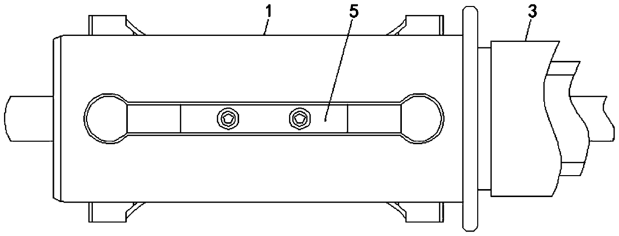
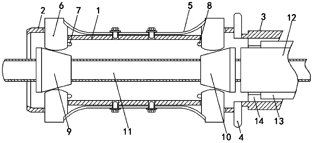
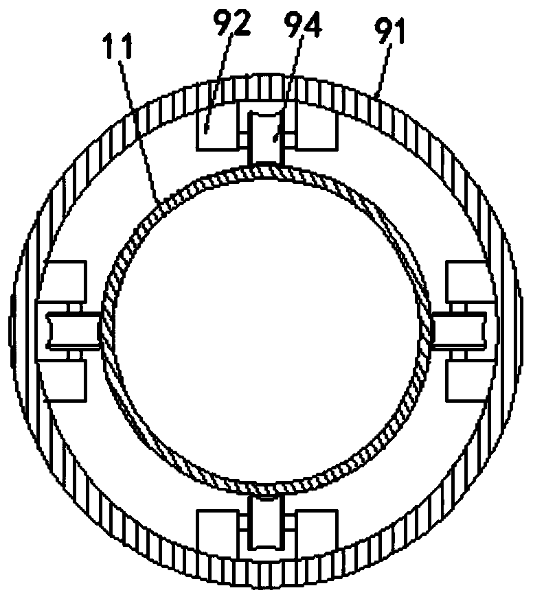
[0033] see Figure 1-8 :

[0034] The optical centering deviation detection device based on the principle of resistivity change includes a housing 1, an inlet port 2, an outlet port 3, a baffle plate 4, a spring leaf 5, a centering block 6, a light source 7, a photoresistor 8, and an inlet positioning mechanism 9. Exit positioning mechanism 10, material 11, fixing mechanism 12, positioning key 13 and keyway 14.

[0035] Wherein: import positioning mechanism 9...


PUM


Abstract

The invention discloses a resistivity variation principle based optical centering deviation detecting device and relates to the technical field of optical centering. The resistivity variation principle based optical centering deviation detecting device comprises a shell; an inlet end and an outlet end are respectively fixedly connected to the left side and the right side of the shell; a baffle isfixedly connected between the shell and the outlet end; four spring sheets are flexibly connected to the outer side of the shell; centering blocks are flexibly connected to the left ends and the rightends of the spring sheets; a light source is flexibly connected to the inner side of each centering block at the left end; and a photoresistance is flexibly connected to the inner side of each centering block at the right side. The height of the light source and the height of the photoresistance are on the same straight line; a material penetrates an inlet positioning mechanism and an outlet positioning mechanism, an outer ring contacts the centering blocks to drive the centering blocks to move when the material shifts and the light source and the photoresistance are not on the same straightline at the moment; whether the material inclines can be detected by utilizing the resistivity variation of the photoresistance; and accuracy and stability of the detection result of the device is improved.

Description

technical field [0001] The invention relates to the technical field of optical centering instruments, in particular to an optical centering deviation detection device based on the principle of resistivity change. Background technique [0002] When carrying out engineering construction or pipeline installation and laying operations, ensuring the concentricity of scaffolding or pipeline installation is an important part of safe production. If the pipeline is not concentric during installation, the pipeline will be offset, which will easily cause the overall displacement or inclination of the scaffolding or pipeline. It affects the safety of construction and the stability of the structure. At the same time, when there is no corresponding detection and early warning device when the pipeline or scaffolding deviates, the early warning cannot be given in time when the safety accident occurs, resulting in the inability of the construction personnel to evacuate in time. security risk...

Claims


Application Information

Patent Timeline
Patent Type & Authority Applications(China)
IPC IPC(8): G01B11/02
CPCG01B11/02
Inventor 孙丽朱芽娣胡巧娣
Owner 涌淳半导体无锡有限公司
Learn More