Multi-antenna optimization method and mobile terminal

A technology of a mobile terminal and an optimization method, applied in the field of communication, can solve the problem of inability to optimize the antenna, and achieve the effect of realizing the antenna

Active Publication Date: 2019-07-19
VIVO MOBILE COMM CO LTD
View PDF6 Cites 9 Cited by
  • Summary
  • Abstract
  • Description
  • Claims
  • Application Information

AI Technical Summary

Problems solved by technology

[0005] The embodiment of the present invention provides a multi-antenna optimization method to solve the problem that the prior art can only perform antenna optimization for specific scenarios, but cannot realize antenna optimization in most scenarios

Method used


Image

  • Multi-antenna optimization method and mobile terminal
  • Multi-antenna optimization method and mobile terminal
  • Multi-antenna optimization method and mobile terminal

Examples


Embodiment Construction

[0020] The following will clearly and completely describe the technical solutions in the embodiments of the present invention with reference to the accompanying drawings in the embodiments of the present invention. Obviously, the described embodiments are some of the embodiments of the present invention, but not all of them. Based on the embodiments of the present invention, all other embodiments obtained by persons of ordinary skill in the art without creative efforts fall within the protection scope of the present invention.

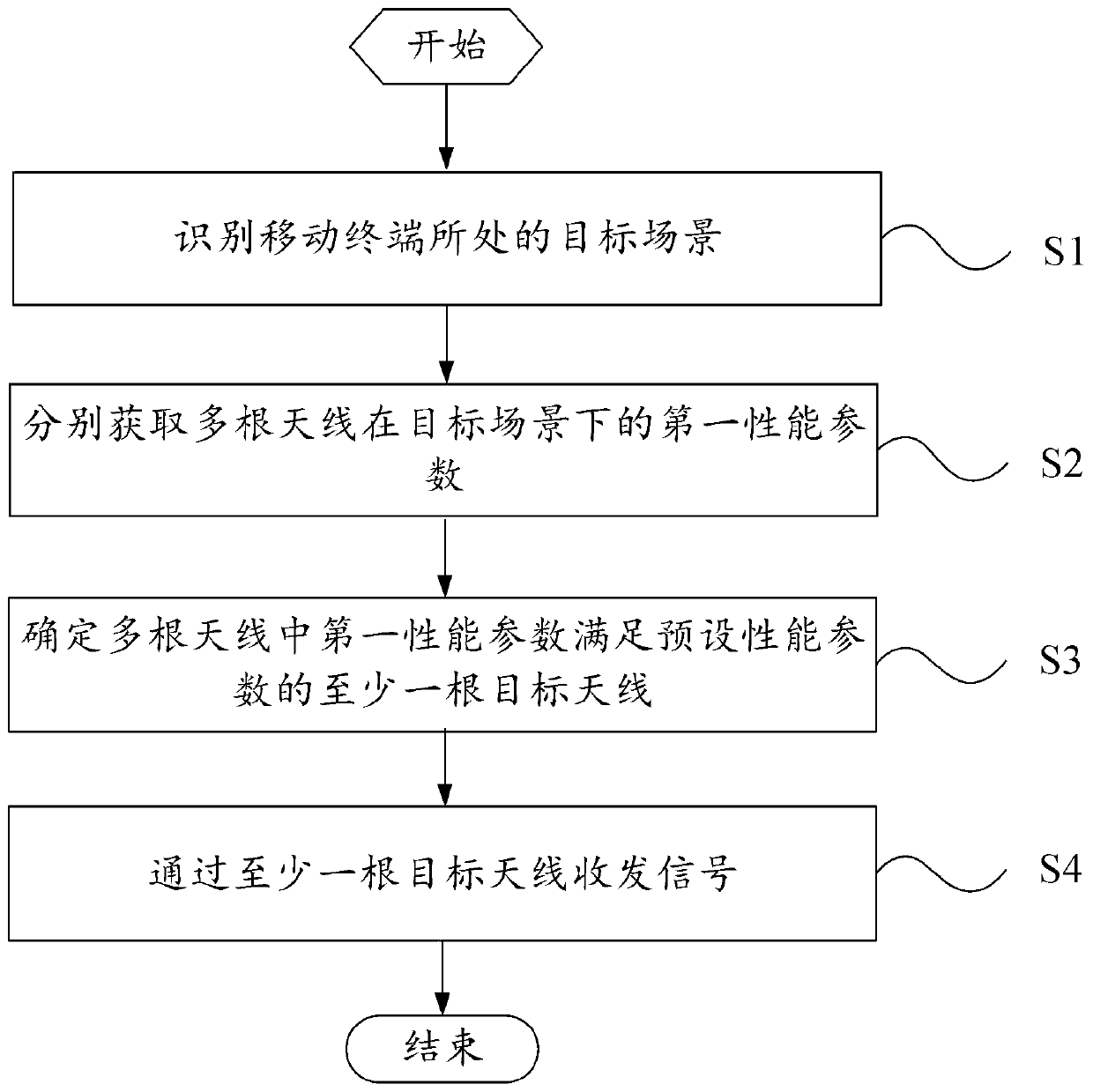
[0021] figure 1 A flowchart showing a multi-antenna optimization method according to an embodiment of the present invention is applied to a mobile terminal, the mobile terminal includes multiple antennas, and the multi-antenna optimization method includes:

[0022] Step S1: Identify the target scene where the mobile terminal is located.

[0023] In this embodiment, different antenna optimization schemes are adopted for different scenarios where the mo...


PUM


Abstract

The embodiment of the invention provides a multi-antenna optimization method and a mobile terminal, relates to the technical field of communication, and aims to solve the problem that antenna optimization cannot be realized in most scenes due to the fact that only antenna optimization can be performed for a specific scene in the prior art. The multi-antenna optimization method comprises the stepsof identifying a target scene where a mobile terminal is located; obtaining first performance parameters of a plurality of antennas of the mobile terminal under the target scene; determining at leastone target antenna of which the first performance parameter satisfies a preset performance parameter in the plurality of antennas; and transmitting and receiving signals through the at least one target antenna. The multi-antenna optimization method provided by the embodiment of the invention is applied to the mobile terminal.

Description

technical field [0001] Embodiments of the present invention relate to the field of communication technologies, and in particular, to a multi-antenna optimization method and a mobile terminal. Background technique [0002] Mobile terminals include antennas for receiving and transmitting signals. Generally, during the process of receiving and transmitting signals, the antenna will be subject to some interference, some interference comes from the outside, and some interference comes from inside the mobile terminal. For example, as the functions of the mobile terminal gradually increase, there are more and more sensors inside the mobile terminal, and these components may become a source of interference for signal transmission and reception. [0003] In view of the above situation, a common solution is to add filter capacitors, notch filters, etc. to the antenna circuit to reduce interference and optimize the antenna. [0004] However, adding filter capacitors, notch filters, e...

Claims


Application Information

Patent Timeline
Patent Type & Authority Applications(China)
IPC IPC(8): H04M1/02H04B7/08H04B7/06H04B7/0404
CPCH04B7/0404H04B7/0608H04B7/0802H04M1/026
Inventor 侯俊海
Owner VIVO MOBILE COMM CO LTD
Why Eureka
Try Eureka