Rotor stator positioning device and its positioning method

A technology of positioning device and rotating stator, which is applied to workpiece clamping devices, manufacturing tools, etc., can solve the problems of low engineering application, difficult positioning, and many factors affecting the pressing of parts, and achieves high operability and simple structure. , the effect of strong practicability

Active Publication Date: 2020-11-20
江苏深蓝航天有限公司
View PDF13 Cites 0 Cited by
  • Summary
  • Abstract
  • Description
  • Claims
  • Application Information

AI Technical Summary

Problems solved by technology

[0004] In order to solve the technical problems such as the difficulty in centering and positioning of the precision rotor of a certain precision turbine machinery, many factors affecting the press-fitting of parts, low engineering applicability, and inability to lean assembly, this application provides a rotor-stator positioning device , the positioning device realizes precise axial and circumferential positioning of the rotor and stator parts at the same time through the precise dimensions of its various parts and its precise connection with the rotor and stator parts. Before adjusting parts), accurately center the rotor and stator parts and control the radial clearance of the rotor and stator, and axially adjust and correct the influence of bearing clearance and part machining error on the axial position and axial clearance. At the same time, during the press-fitting process Precisely control the rotor-stator gap, so as to achieve the purpose of centering, distance adjustment, anti-rotation, improve the quality of rotor-stator pressing, and realize lean assembly

Method used


Image

  • Rotor stator positioning device and its positioning method
  • Rotor stator positioning device and its positioning method
  • Rotor stator positioning device and its positioning method

Examples


Embodiment Construction

[0040] The present application will be further described in detail below in conjunction with the accompanying drawings and embodiments. It should be understood that the specific implementation manners described here are only used to explain relevant content, rather than to limit the present application. In addition, it should be noted that, for ease of description, only parts relevant to the present application are shown in the drawings.

[0041] It should be noted that, in the case of no conflict, the implementations in the present application and the features in the implementations can be combined with each other. Hereinafter, the present application will be described in detail with reference to the accompanying drawings and in combination with embodiments.

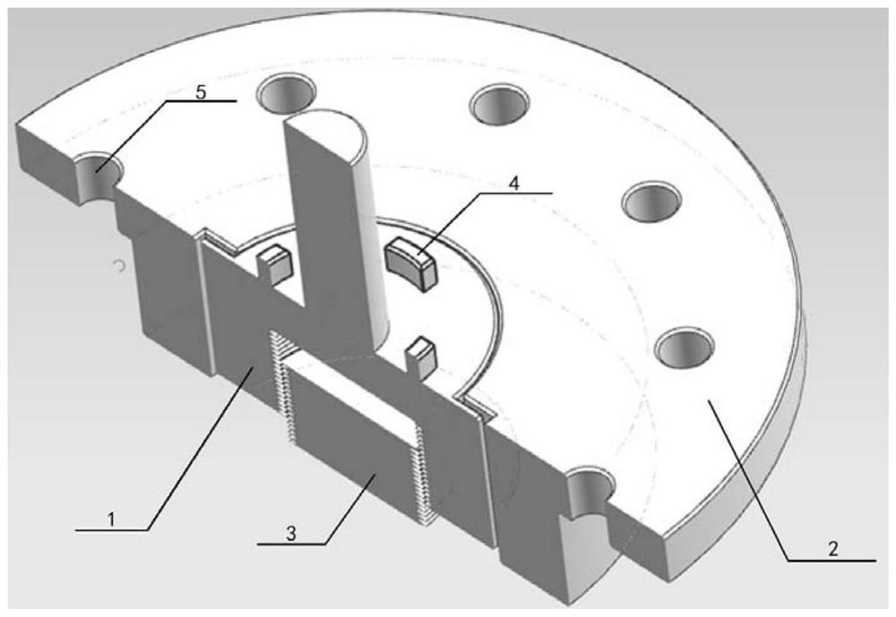
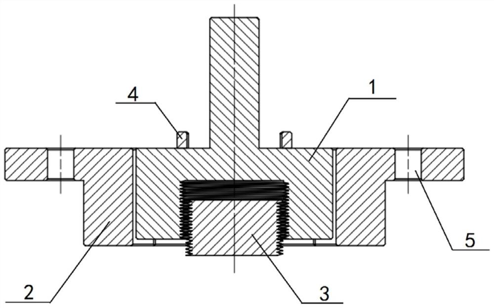
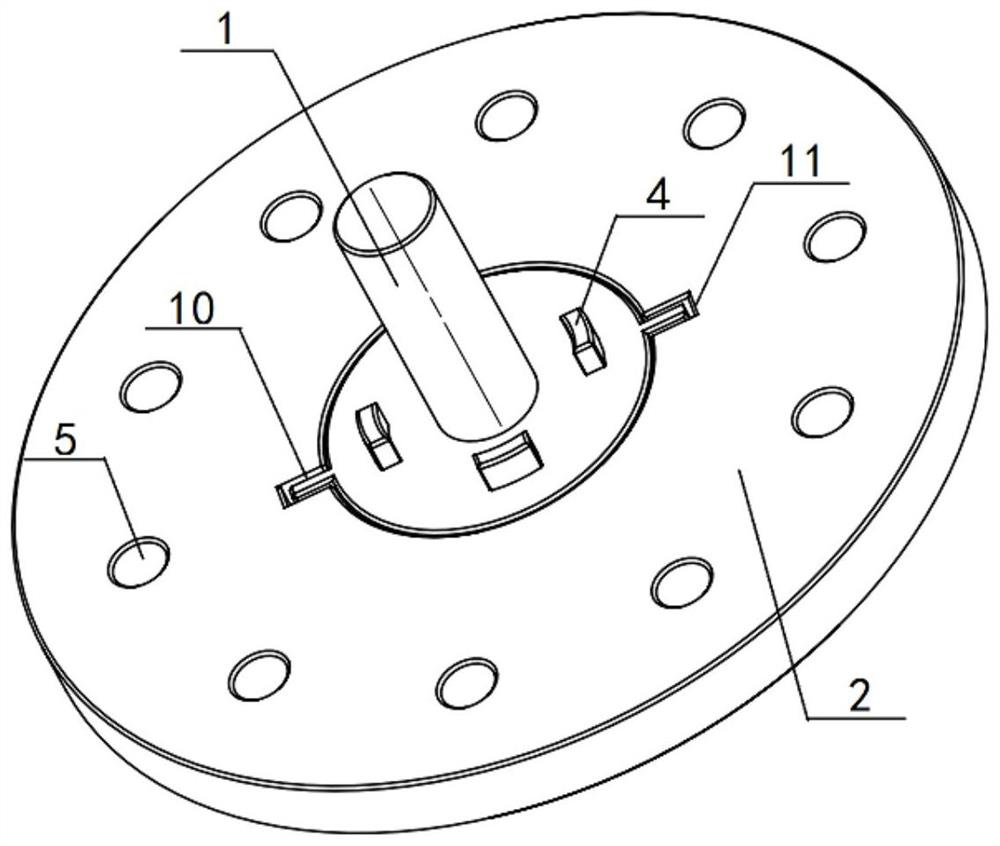
[0042] From figure 1 and figure 2 It can be seen from the figure that the rotor-stator positioning device of the present application includes an inner half 1 , an outer half 2 and precision fine-tuning bolts 3 .

...


PUM


Abstract

The invention provides a rotor and stator locating device comprising an inner half, an outer half and a precise fine adjustment bolt, wherein the inner half comprises a precise shaft, a first limitingstructure and a second limiting structure. The precise shaft is matched with an axial hole of a rotor part and controls the radial clearance of the rotor part and a stator part. The first limiting structure is in matched connection with the outer half. The second limiting structure is connected with the rotor part. The outer half comprises a third limiting structure in matched connection with theinner half, and a fourth limiting structure used for being connected with the stator part. The precise fine adjustment bolt is in threaded connection with the inner half so as to axially precisely locate the rotor part and to precisely control the axial clearance of the rotor part and the stator part. In addition, the invention further relates to a method for rotor and stator locating through therotor and stator locating device.

Description

technical field [0001] The present application relates to a rotor-stator positioning device and a positioning method thereof, in particular to an aerospace engine precision rotor-stator positioning device and a positioning method thereof which require precise axial and circumferential positioning at the same time, and belongs to the field of turbomachinery assembly. Background technique [0002] As one of the key components of energy conversion, turbomachinery is widely used in aerospace and other mechanical fields. The assembly of turbomachinery is an important link in the production of turbomachinery. Its assembly quality has a non-negligible impact on the realization of product performance, and its assembly efficiency is one of the restrictive factors for product engineering application. [0003] When the rotor part and the stator part of the turbomachinery are press-fitted, the parts that match the rotor-stator are generally press-fitted on the rotor shaft, and the parts...

Claims


Application Information

Patent Timeline
Patent Type & Authority Patents(China)
IPC IPC(8): B25B11/02
CPCB25B11/02
Inventor 不公告发明人
Owner 江苏深蓝航天有限公司
Why Eureka
Try Eureka