

Compact large-field-angle near-eye display device based on total reflection
A near-eye display and field of view technology, which is applied in optics, instruments, optical components, etc., can solve the problems that it is difficult to make thin and compact glasses-type displays, and achieve the effect of large field of view and large near-eye display effect
- Summary
- Abstract
- Description
- Claims
- Application Information
AI Technical Summary
Problems solved by technology
Method used
Image

Examples
Embodiment 1
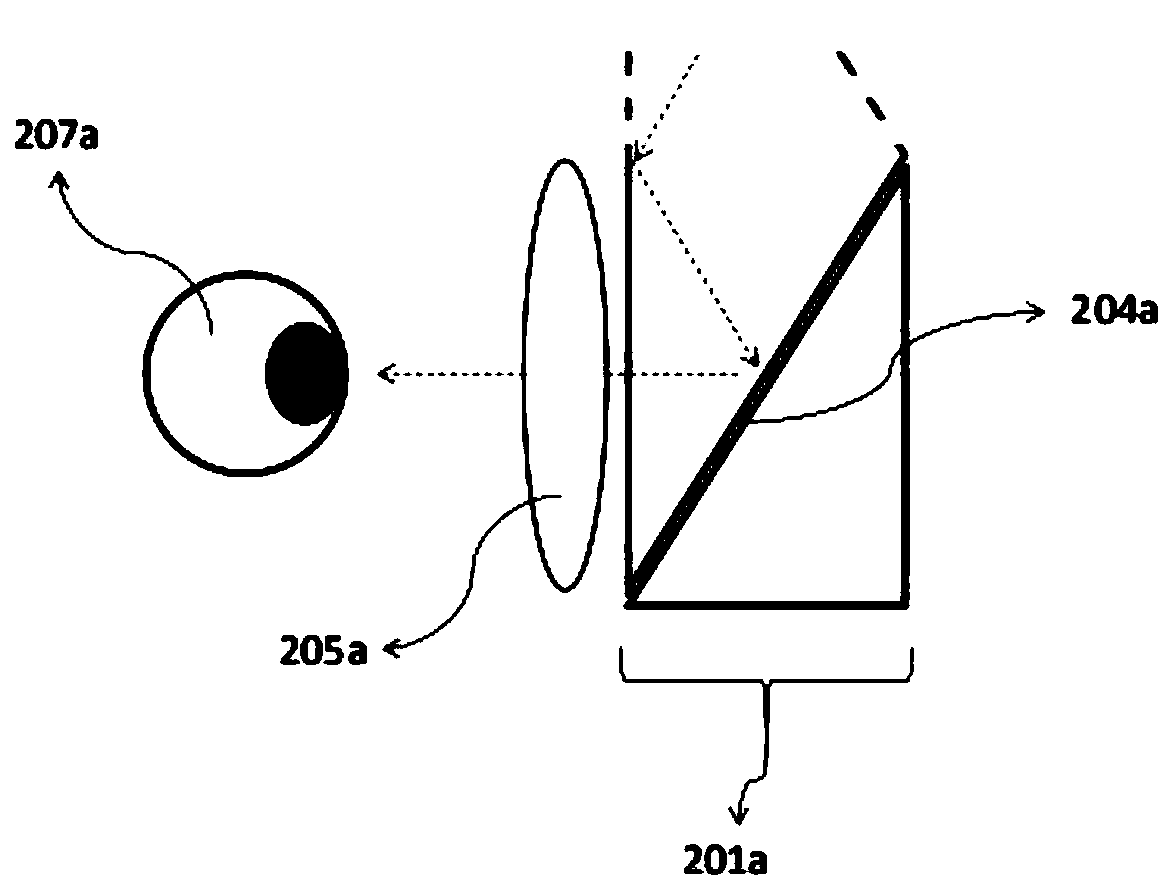
[0037] Figure 2a ~ Figure 2f Shown is a schematic structural diagram of various types of total reflection prisms and near-eye refractive components in the compact large-field-of-view near-eye display device based on total reflection in the first embodiment of the present invention.
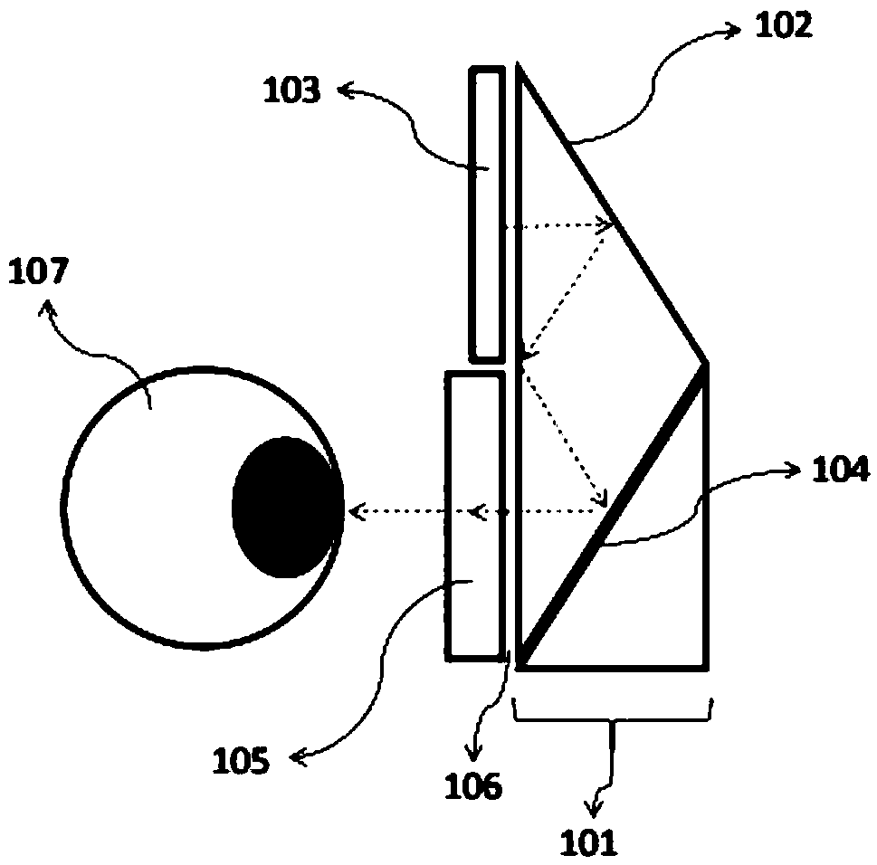
[0038] In this embodiment, the light emitted by the image source is reflected by the secondary reflection surface, and then enters the near-eye refractive component for image amplification, and finally enters the human eye, thereby achieving a near-eye display effect with a large viewing angle in a compact volume.
[0039] Such as Figure 2a As shown, the near-eye refractive component can adopt a positive focal length lens 205a.
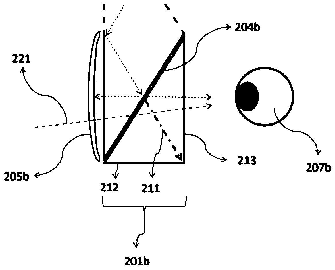
[0040] Such as Figure 2b ~ Figure 2eAs shown, the near-eye refractive component can allow the external ambient light 221 to pass through without diopter, and the secondary reflection surface is semi-reflective (such as a semi-reflective film, a polarization splitting...
Embodiment 2
[0057] Figure 3a ~ Figure 3f Shown are various types of specific structural schematic diagrams of the total reflection optical system in the compact large viewing angle near-eye display device based on total reflection according to the second embodiment of the present invention.
[0058] In this embodiment, the total reflection prism 301 has different shapes, and the light emitted by the image source can be totally reflected once, or twice, or three times during the light transmission process, thereby forming different total reflection optical systems .
[0059] Such as Figure 3a , the light is totally reflected twice.
[0060] Such as Figure 3b , the light is totally reflected three times and reflected by the end reflection surface 308b.
[0061] Such as Figure 3c , the light is totally reflected three times and reflected by the end reflection surface 308c.
[0062] Such as Figure 3d , the light is totally reflected twice and reflected by the end reflection surfac...
Embodiment 3
[0066] Figure 4a ~ Figure 4b Shown is a schematic diagram of the situation that the total reflection prism in the compact large viewing angle near-eye display device based on total reflection in the third embodiment of the present invention includes a compensation surface.
[0067] The compensation surface is a curved surface, which is located on the side of the total reflection prism facing away from the near-eye refractive component, and adopts a curved surface (spherical, aspheric or other curved surface), thereby producing a certain diopter, which can cooperate with the refractive surface of the near-eye refractive component , so that the internal display light and the external ambient light are refracted and adjusted, and can adapt to users with different eyesight.
[0068] Such as Figure 4a , the positive focal length lens 405a is used as the near-eye refractive component, so that the compensation surface 409a has a diopter reduction effect on the outside to offset th...
PUM
 Abstract
Description
Claims
Application Information