Limit shock absorber structure
A shock absorber and fixed tube technology, applied in the direction of shock absorber, spring/shock absorber, shock absorber, etc., can solve the problems of inconvenient adjustment of feedback time, inconvenient reduction of length, inconvenient two-way shock absorption, etc. Achieve good shock absorption effect, save space and prolong service life
- Summary
- Abstract
- Description
- Claims
- Application Information
AI Technical Summary
Problems solved by technology
Method used
Image
Examples
Embodiment 1
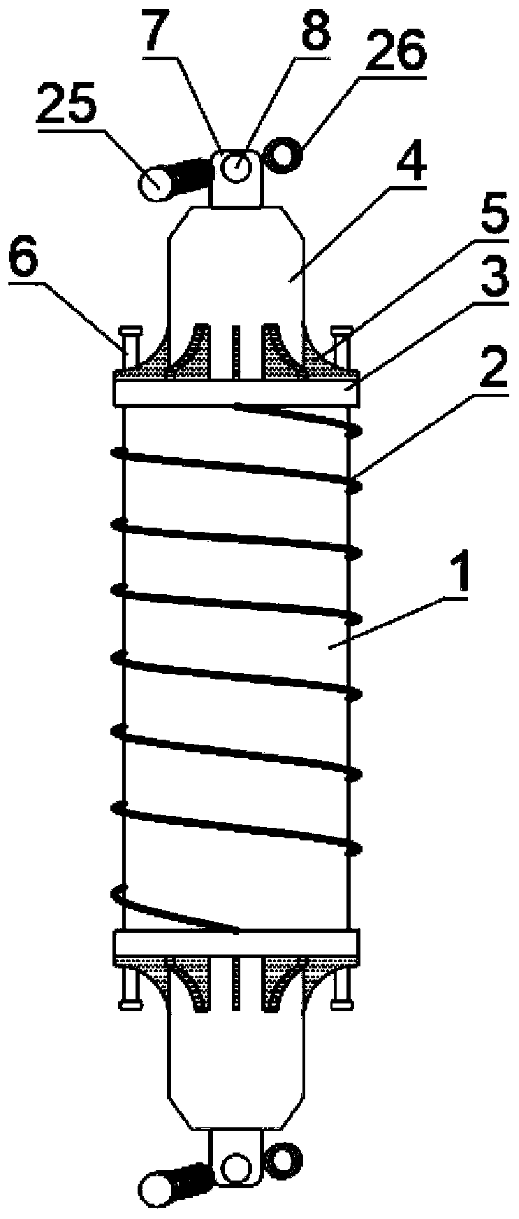
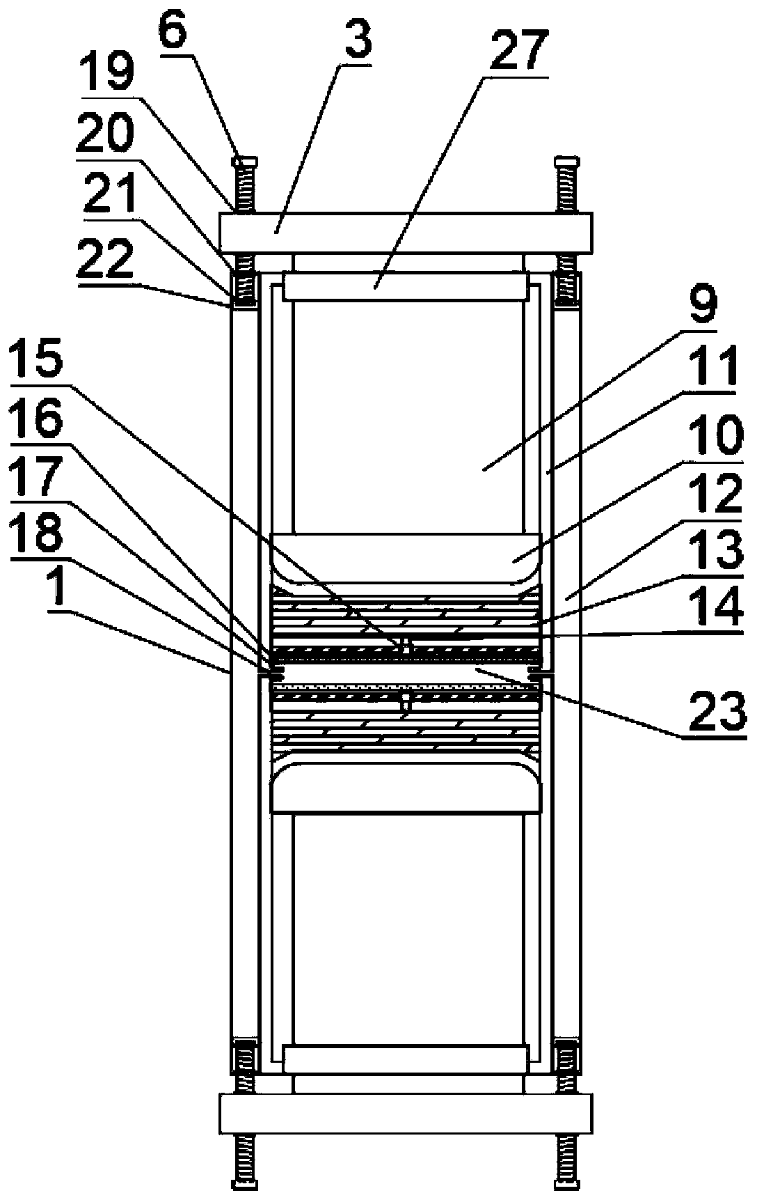
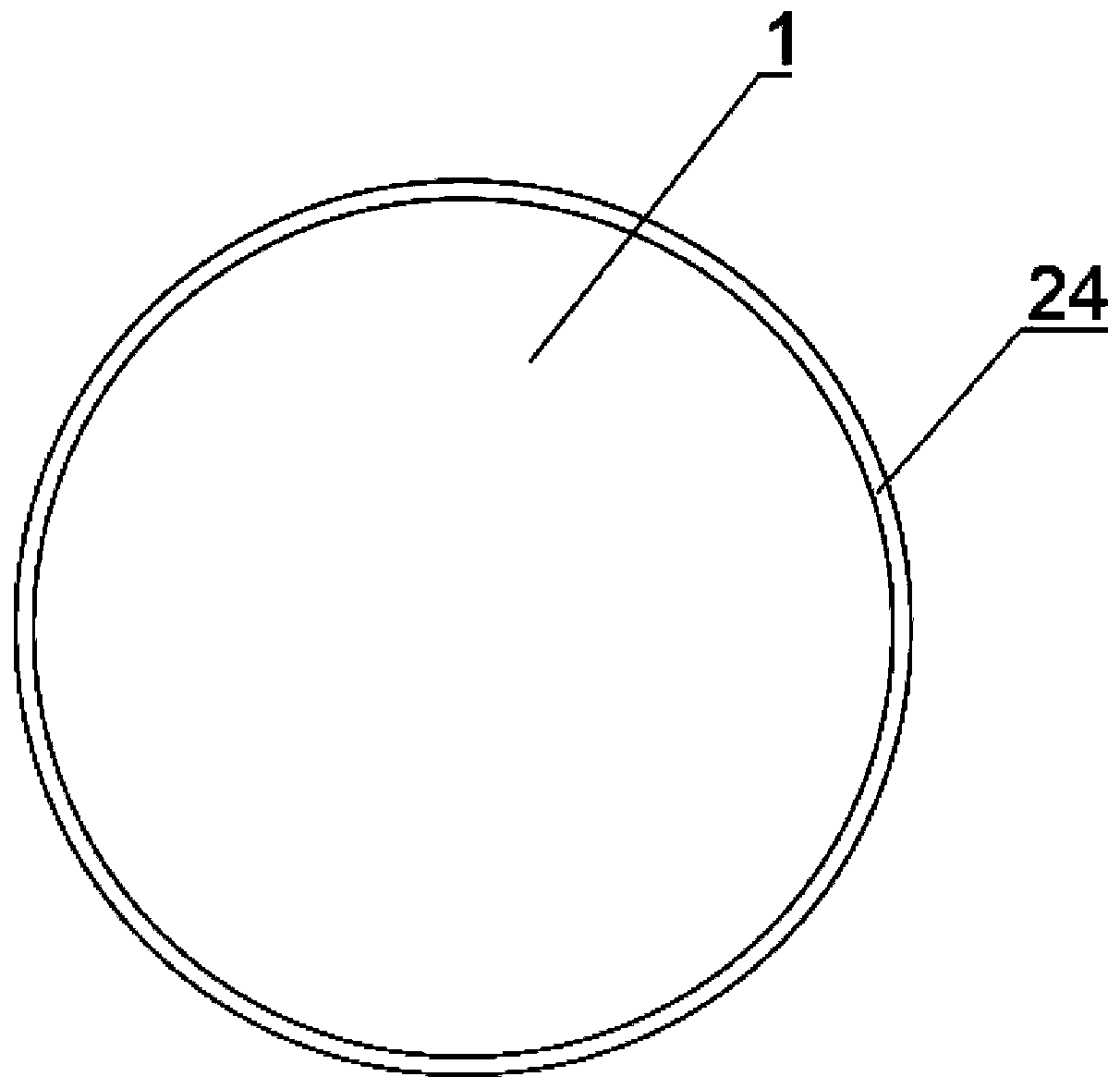
[0022] Such as Figure 1-3 As shown, a limit shock absorber structure includes a fixed cylinder 1, a spring 2 and a fixed disk 3. The fixed cylinder 1 is composed of an inner cylinder 11 and an outer cavity 12, and the fixed cylinder 1 has two bottom and top portions. A force post 9 is installed at both ends through a reserved groove 27, the force post 9 is located in the inner cylinder 1, one end of the force post 9 is connected with a movable plug 10, and a buffer block 13 is provided inside the movable plug 10, A hollow cavity 23 is arranged between the buffer blocks 13. The bottom and top of the hollow cavity 23 are both installed with a top post 14 through a sleeve hole 15. One end of the top post 14 is connected to the buffer block 13, and the other end of the top post 14 is located in the hollow A pressure plate 16 is connected to the cavity 23. An infusion tube 18 is opened at both ends of the hollow cavity 23, and one end of the infusion tube 18 is connected to the out...
Embodiment 2
[0034] Such as Figure 1-3 As shown, a limit shock absorber structure includes a fixed cylinder 1, a spring 2 and a fixed disk 3. The fixed cylinder 1 is composed of an inner cylinder 11 and an outer cavity 12, and the fixed cylinder 1 has two bottom and top portions. A force post 9 is installed at both ends through a reserved groove 27, the force post 9 is located in the inner cylinder 1, one end of the force post 9 is connected with a movable plug 10, and a buffer block 13 is provided inside the movable plug 10, A hollow cavity 23 is arranged between the buffer blocks 13. The bottom and top of the hollow cavity 23 are both installed with a top post 14 through a sleeve hole 15. One end of the top post 14 is connected to the buffer block 13, and the other end of the top post 14 is located in the hollow A pressure plate 16 is connected to the cavity 23. An infusion tube 18 is opened at both ends of the hollow cavity 23, and one end of the infusion tube 18 is connected to the out...
PUM
 Abstract
Description
Claims
Application Information
 - R&D
- Intellectual Property
- Life Sciences
- Materials
- Tech Scout
- Unparalleled Data Quality
- Higher Quality Content
- 60% Fewer Hallucinations
Browse by: Latest US Patents, China's latest patents, Technical Efficacy Thesaurus, Application Domain, Technology Topic, Popular Technical Reports.
© 2025 PatSnap. All rights reserved.Legal|Privacy policy|Modern Slavery Act Transparency Statement|Sitemap|About US| Contact US: help@patsnap.com


