A limit shock absorber structure

A shock absorber and fixed cylinder technology, applied in the direction of shock absorber, spring/shock absorber, shock absorber, etc., can solve the problems of inconvenient adjustment of feedback time, inconvenient two-way shock absorption, inconvenient length reduction, etc. Achieve the effect of good shock absorption, save space and reduce the overall height

Active Publication Date: 2021-12-31
BOHAN QUANZHOU MACHINERY CO LTD
View PDF14 Cites 0 Cited by
  • Summary
  • Abstract
  • Description
  • Claims
  • Application Information

AI Technical Summary

Problems solved by technology

[0002] In industries such as motorcycles and automobiles, the so-called shock absorber mechanism is very necessary for shock absorption. The previous shock absorber mechanism cannot conveniently perform two-way shock absorption, reduce the length easily, and adjust the feedback time conveniently. , the overall strength is low, so we propose a limit shock absorber structure

Method used


Image

  • A limit shock absorber structure
  • A limit shock absorber structure
  • A limit shock absorber structure

Examples


Embodiment 1

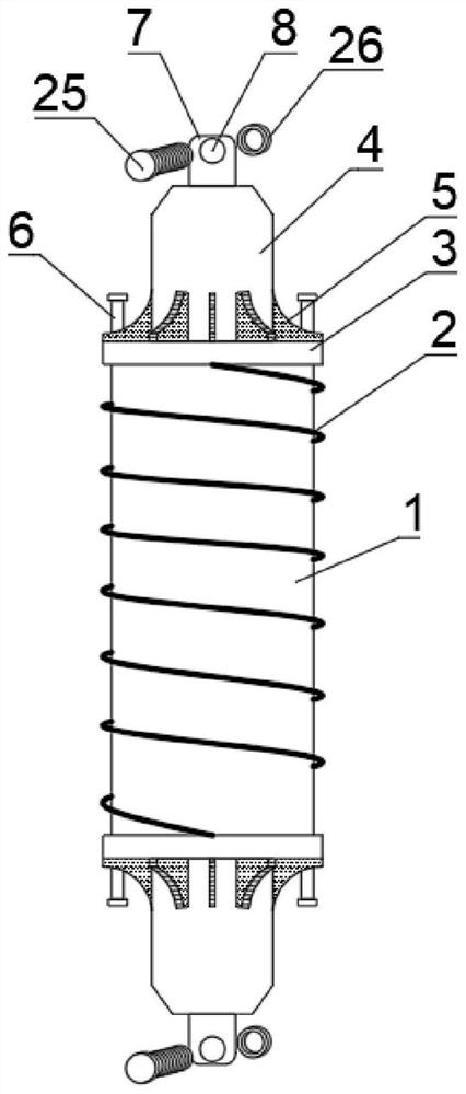
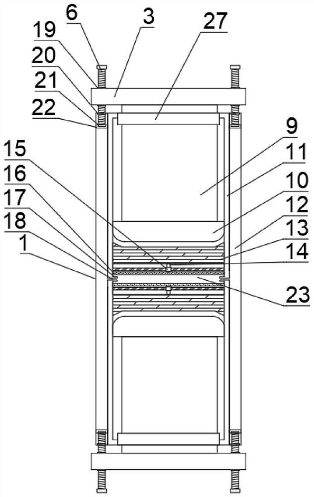
[0021] Such as Figure 1-3 As shown, a position-limiting shock absorber structure includes a fixed cylinder 1, a spring 2 and a fixed plate 3. The fixed cylinder 1 is composed of an inner cylinder 11 and an outer cavity 12. The bottom and top of the fixed cylinder 1 are two Both ends are equipped with a force column 9 through a reserved groove 27, the force column 9 is located in the inner cylinder 11, one end of the force column 9 is connected to a movable plug 10, and the inside of the movable plug 10 is provided with a buffer block 13. A hollow cavity 23 is provided between the buffer blocks 13, the bottom and the top of the hollow cavity 23 are equipped with a jack post 14 through the sleeve hole 15, one end of the jack post 14 is connected to the buffer block 13, and the other end of the jack post 14 is located in the hollow The cavity 23 is connected with a pressure plate 16, the two ends of the hollow cavity 23 are provided with an infusion tube 18 and one end of the in...

Embodiment 2

[0031] Such as Figure 1-3 As shown, a position-limiting shock absorber structure includes a fixed cylinder 1, a spring 2 and a fixed plate 3. The fixed cylinder 1 is composed of an inner cylinder 11 and an outer cavity 12. The bottom and top of the fixed cylinder 1 are two Both ends are equipped with a force column 9 through a reserved groove 27, the force column 9 is located in the inner cylinder 11, one end of the force column 9 is connected to a movable plug 10, and the inside of the movable plug 10 is provided with a buffer block 13. A hollow cavity 23 is provided between the buffer blocks 13, the bottom and the top of the hollow cavity 23 are equipped with a jack post 14 through the sleeve hole 15, one end of the jack post 14 is connected to the buffer block 13, and the other end of the jack post 14 is located in the hollow The cavity 23 is connected with a pressure plate 16, the two ends of the hollow cavity 23 are provided with an infusion tube 18 and one end of the in...


PUM


Abstract

The invention discloses a position-limiting shock absorber structure, which includes a fixed cylinder, a spring and a fixed plate. The fixed cylinder is composed of an inner cylinder body and an outer cavity, and both ends of the bottom and top of the fixed cylinder pass through reserved grooves. A force column is installed, the force column is located in the inner cylinder, a movable plug is connected to one end of the force column, a buffer block is arranged inside the movable plug, a hollow cavity is arranged between the buffer blocks, the bottom of the hollow cavity and The tops are equipped with jacking posts through sleeve holes, one end of the jacking pins is connected to the buffer block, the other end of the jacking pins is located in the hollow cavity and connected with a pressure plate, and the two ends of the hollow cavity are provided with infusion tubes, and one end of the infusion tubes is connected to the outer tube. A cavity, a fixing block is arranged on the outside of the fixing cylinder, and a reinforcing layer is arranged on the outer surface of the fixing cylinder. The invention can conveniently carry out two-way shock absorption, can also conveniently reduce the length, can conveniently adjust the feedback time, has high overall strength, and is suitable for being widely popularized and used.

Description

technical field [0001] The invention relates to the technical field of shock absorbers, in particular to a limit shock absorber structure. Background technique [0002] In industries such as motorcycles and automobiles, the so-called shock absorber mechanism is very necessary for shock absorption. The previous shock absorber mechanism cannot conveniently perform two-way shock absorption, reduce the length easily, and adjust the feedback time conveniently. , the overall strength is low, so we propose a limit shock absorber structure. Contents of the invention [0003] The main purpose of the present invention is to provide a position-limiting shock absorber structure, by installing power columns at both ends of the top and bottom of the fixed cylinder, and using the fixed plates on the top and bottom of the fixed cylinder to simultaneously push the corresponding force columns, bidirectional Shock absorption, the shock absorption effect is better. By setting the outer cavit...

Claims


Application Information

Patent Timeline
Patent Type & Authority Patents(China)
IPC IPC(8): F16F9/18F16F9/58
CPCF16F9/18F16F9/58
Inventor 吴金钟李红
Owner BOHAN QUANZHOU MACHINERY CO LTD
Why Eureka
Try Eureka